Flexible Insulation Membrane With Flat Overlapping Joints and Method of Installing the Same

a flexible insulation and joint technology, applied in the field of membranes, can solve the problems of floor surface not being able to tolerate the presence of bumps, limitation is a major drawback in the use of such membranes, and the foundation limitation of the way moisture barriers are installed

Inactive Publication Date: 2007-10-04
PLANTE REJEAN
View PDF13 Cites 26 Cited by
  • Summary
  • Abstract
  • Description
  • Claims
  • Application Information

AI Technical Summary

Benefits of technology

[0011] It is another aim of the present invention to provide a new moisture barrier membrane to help equalize moisture levels between the top and bottom layers of a floor surface.
[0016] In accordance with a further general aspect of the present invention, there is provided a moisture barrier underlayment adapted to be installed on a subfloor to provide a substantially flat and level surface for receiving floor covering, comprising at least first and second strips of moisture barrier membranes laid down one next to the other in a coplanar relationship, said first and second strips having a thickness W1, and an overlap joint between said first and second strips, said overlap joint having a thickness W2 substantially equal to or less than W1 and providing a free-bump transition between said first and second strips while preventing straight-through moisture infiltration from the subfloor to the floor covering.
[0017] In accordance with a still further general aspect of the present invention, there is provided a floor arrangement adapted to be installed over a subfloor, comprising flexible flooring members adapted to be laid one next to the other in a coplanar relationship over the subfloor, said flexible flooring members having a thickness W1, and an overlap joint between each pair of adjacent flexible flooring members, said overlap joint having a thickness W2 substantially equal to or less than W1 and providing a free-bump transition between said flexible flooring members.

Problems solved by technology

A fundamental limitation in the way moisture barriers are installed requires a bump producing overlap of the joints.
This limitation is a major drawback in the use of such membranes in the flooring trade.
Indeed, a floor surface cannot tolerate the presence of a bump underneath a floor surface since that bump transfers to the floor surface.
Even for roofs the presence of bumps can become a problem since it is often required for workers to walk on roof surfaces such as when maintaining air conditioning units or other such pieces of equipment found on roofs.
Walking across bumps or dragging and carrying equipment across bumps can damage the overlap and which can result in a leak.
The moisture barrier membrane arrangements currently used underneath ceramic tiles present some bumps (i.e. an uneven top surface) which result in mechanical weaknesses.
That is useful for short term fluctuations in moisture levels but in areas where moisture such as from an unheated basement is present at a high level for weeks or even months, this can cause serious warping on a wooden floor since, over time, moisture will pass through the moisture retarder and infiltrate the wood fibers.
Moisture coming from underneath is very difficult to control and thus far, the only practical solution appears to be moisture retarder which have the problem of having moisture leaks occurring at the joints between strips of the membrane that are not sealed but merely overlapped.
To overcome this, some membranes use taped joints but the tape can, over time, deteriorate and become useless, thus exposing opened joints.
Sound insulation membranes also suffer from sounds infiltration between adjacent membranes or layers of insulation material.

Method used


Image

  • Flexible Insulation Membrane With Flat Overlapping Joints and Method of Installing the Same
  • Flexible Insulation Membrane With Flat Overlapping Joints and Method of Installing the Same
  • Flexible Insulation Membrane With Flat Overlapping Joints and Method of Installing the Same

Examples


Embodiment Construction

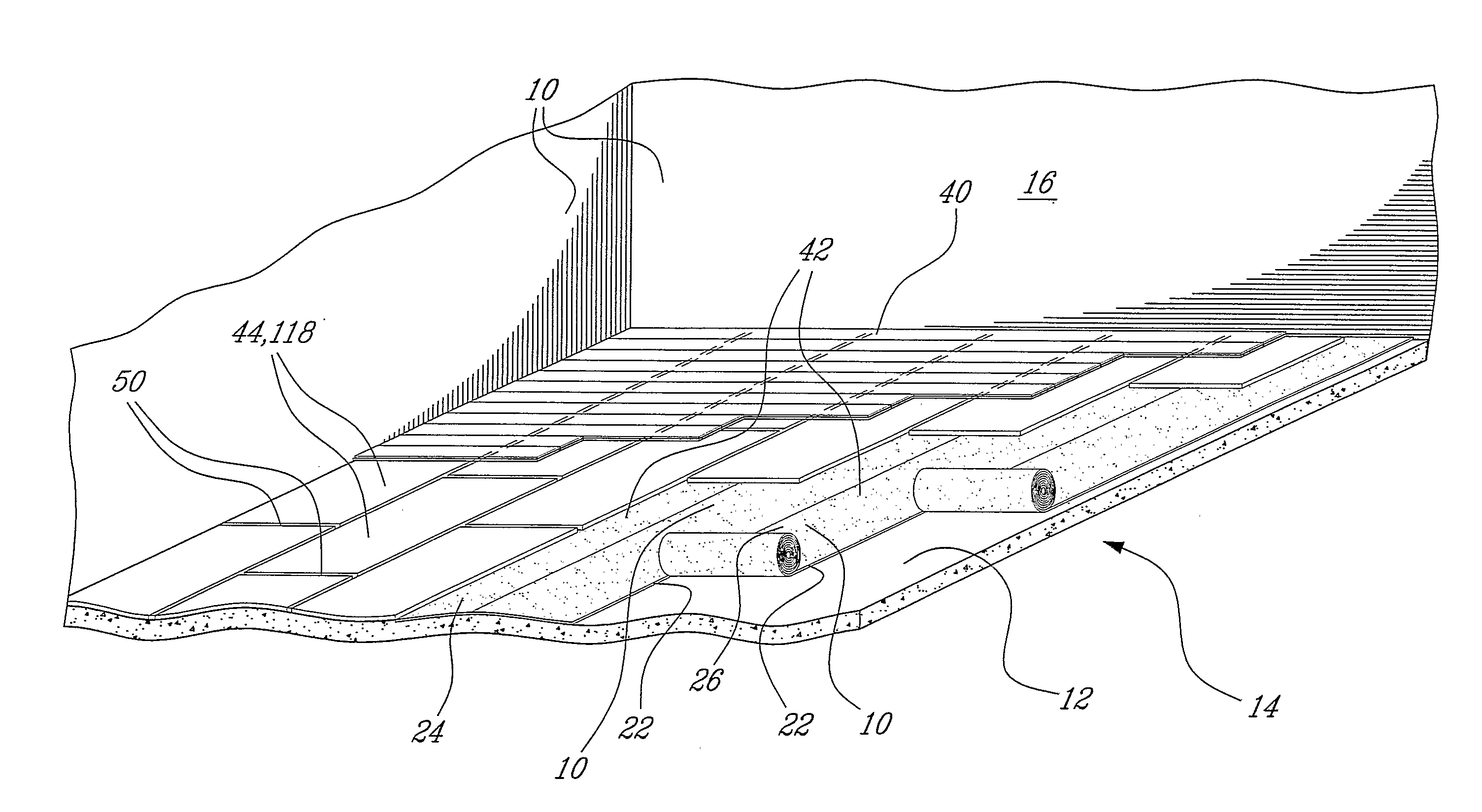
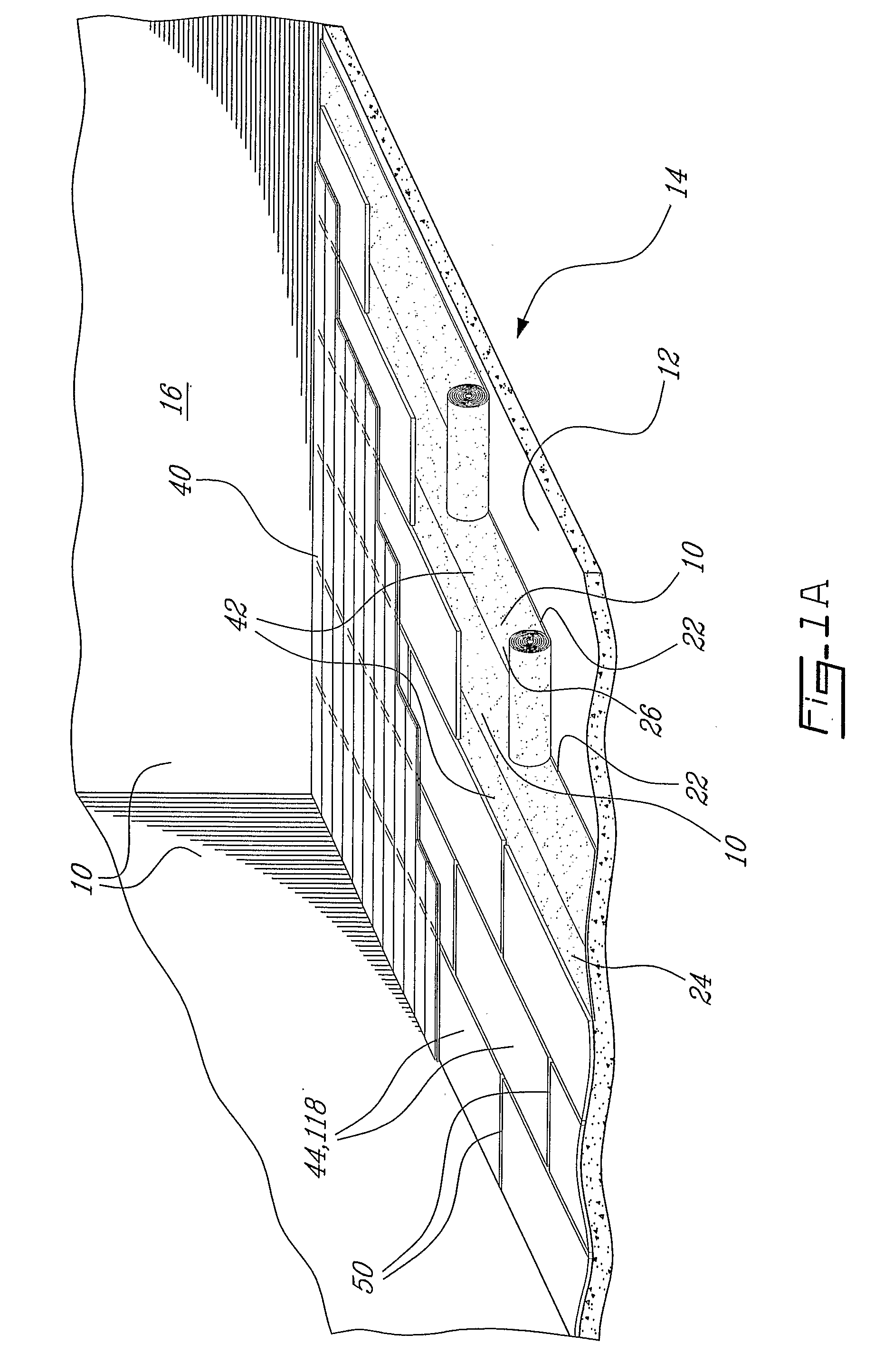
[0037]FIG. 1a illustrates a floor assembly wherein rolls of flexible moisture barrier membrane are laid down on a subfloor (12) and then covered with a layer of intermediate floor panels (44) on which floor boards (40) (in the illustrated example wood planks) are installed. In the case of FIG. 1a, the subfloor (12) is concrete but it could be any type of material commonly used as subfloor material such as plywood, and is either the subfloor of a basement or the subfloor (12) of a multi storey concrete structure building. In both cases, concrete is known for holding moisture over a long period of time and the problem is compounded when a slab of concrete is laid directly over a soil (14) that has high water content.

[0038] Since moisture content (MC) coming from underneath and through the subfloor (12) can be, at times, much higher than the MC in the ambient air (16) above the subfloor (12), that is the ambient air (16) in a given room, it is wise to block the ingress of moisture fro...


PUM

PropertyMeasurementUnit
widthaaaaaaaaaa
widthaaaaaaaaaa
thicknessaaaaaaaaaa

Abstract

A sound and / or moisture barrier underlayment suited for use on a roof or floor surface to provide a substantially flat and level surface, comprises at least first and second strips of insulation membranes (10) laid down one next to the other in a coplanar relationship. The first and second strips (24, 26) have a thickness W1. An overlap joint (28) is provided between the first and second strips (24, 26). The overlap joint (28) has a thickness W2 substantially equal to or less than W1 to provide a free-bump transition between the first and second strips (24, 26) while preventing straight-through infiltration.

Description

BACKGROUND OF THE INVENTION [0001] 1. Field of the Invention [0002] This invention relates generally to membranes suited for use as water / moisture barrier or sound insulation in roofing, flooring and other related applications. [0003] 2. Description of the Prior Art [0004] The prior art reveals the use of moisture barriers chiefly aimed at the roofing trade. A fundamental limitation in the way moisture barriers are installed requires a bump producing overlap of the joints. This limitation is a major drawback in the use of such membranes in the flooring trade. Indeed, a floor surface cannot tolerate the presence of a bump underneath a floor surface since that bump transfers to the floor surface. Even for roofs the presence of bumps can become a problem since it is often required for workers to walk on roof surfaces such as when maintaining air conditioning units or other such pieces of equipment found on roofs. Walking across bumps or dragging and carrying equipment across bumps can ...

Claims


Application Information

Patent Timeline
Patent Type & Authority Applications(United States)
IPC IPC(8): E04B1/64B32B3/02E04B1/62E04B1/66E04B1/68E04B1/74E04B1/84E04D5/02E04D5/12E04D5/14E04D13/16E04F15/04E04F15/18
CPCB32B3/02Y10T428/192E04B1/68E04B1/8409E04D5/12E04D5/149E04D12/002E04F15/04E04F15/18E04F15/181E04F19/045E04F21/0092E04F2201/026E04F2290/043E04B1/66E04B1/665E04F15/185E04F15/187E04F15/182E04F15/203B32B2471/00B32B7/06B32B2307/7265B32B11/04B32B2395/00B32B2307/748B32B2307/102
Inventor PLANTE, REJEAN
Owner PLANTE REJEAN
Why Eureka
Try Eureka