
Modular solar energy-collecting enclosure element, and modular system for forming solar energy-collecting enclosures on buildings

a solar energy and enclosure element technology, applied in the direction of solar heat collectors with working fluids, sustainable buildings, collector casings, etc., can solve the problems of increasing the final cost of products, welds, and weak joints between plates using adhesives,

Inactive Publication Date: 2007-10-04
GARCIA CORS JOSEP +1
View PDF11 Cites 22 Cited by
  • Summary
  • Abstract
  • Description
  • Claims
  • Application Information

AI Technical Summary

Benefits of technology

[0010] One aspect of the present invention provides a modular enclosure solar energy-collector element that can be produced from two facing plates in a relative simple manner, having sufficient strength to be self-supporting and provided, at both longitudinal and transversal edges in relation to the direction of a possible flow of water over it, with configurations for leak-tight joining to other adjacent elements, whether these are modular solar energy-collecting enclosure modules or simply complementary enclosure elements.
[0017] In an exemplary embodiment, the inner plate of the modular solar energy-collecting enclosure element, in accordance with this invention, includes heat insulation sheets housed between the mentioned reinforcement members, with their ends matched to the flaps and folds. The assembly may be closed by some means that act as a vapour barrier and / or to prevent any possible thermal bridges and / or against fire. Because of this the modular solar energy-collecting enclosure element incorporates all the necessary elements for a building enclosure and for a solar heat-energy collector, so that it is completely suitable for direct installation onto a sub-structure, it is self-supporting in order to withstand the required structural stresses of a roof or façade and efficiently complies with the two cited functions integrated into a single modular element.
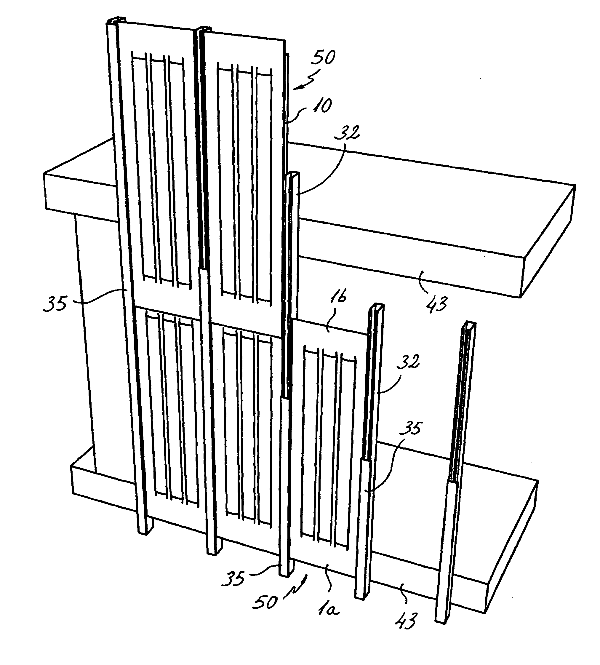
[0020] Thereby, an enclosure produced using the system of this invention has several advantages. On the one hand, since the actual solar energy-collecting surface, in other words, the outer plate, is shaped at its longitudinal and transversal edges for coupling to the outer plates of the adjacent enclosure elements, a solid and waterproof joint is obtained between all enclosure elements, whether these are solar energy collectors or complementary enclosure elements, which guarantees a waterproof system. Moreover, all the elements related with the solar energy-collecting installation are hidden from view, so that when the system is employed as a roof, it still offers the appearance of a traditional clear roof, without any piping, connections, joint profiles or other heat-carrying fluid primary circuit elements being visible. When the system is employed as a façade, it provides an equally clear appearance, which is also both functional and modern. On the other hand, thanks to stiffening elements that are incorporated into the modular elements, when the system forms a roof, this is walkable, for example, to facilitate its maintenance, together with the maintenance of the heat-carrying fluid primary circuit, which comprises piping housed inside profiles that are accessible from the outside.

Problems solved by technology

The specification in this document does not describe nor suggest the use of said collector as a self-supporting element forming a roof and the mentioned joints between the plates using adhesive could turn out to be too weak if employed for this purpose.
As a solar energy collector, the construction using corrugated plates leaves all the ends of the channels open, which must be then connected by means of, for example, collecting and distributing ducts for collector operation, which entails a significant amount of work, which would increase the final cost of the product.
However, the welds, especially in the areas between the depressions, are quite difficult and slow to produce.
On the other hand, the seaming of only the peripheral edges does not ensure sufficient strength for the assembly to perform a function, for example, of self-supporting roof, nor does it guarantee the leak-tightness between the channels with the element serving as a solar energy collector.
Aforementioned drawbacks associated with welding persists in this construction; namely, the welding operation that is both costly in time and money, the difficulty in checking the leak-tightness and the excessive heating of the plates during welding.
In addition, the suggested press-formed shapes, which consist of separate squares or rectangles, geometrically distributed over the plates, do not provide any significant increase in the stiffness of each of the plates in any given direction, so that the increase in rigidity of the two joined plates is only the sum of strength of the two superposed plates without any two-dimensional cooperation between them in order to increase this strength.
However, the construction of each of said panels involves the manufacture, assembly and joining of multiple parts, which increases the costs of the end product.
However, this does not resolve the butt joining between modules at their longitudinal ends, in the direction of roof slope, which means the slope has to be covered by a single panel along its entire length.
This means that the panels have to be manufactured in a single piece to cover the full length of the roof, which then either limits the length of roof to be covered or significantly long panels have to be manufactured which, on the one hand, complicate the production process and, on the other, reduce the energy-collecting performance.
This is due to the fact that the heat-carrying fluid circulating inside the panel absorbs the greatest amount of heat that it is able to absorb in the approximately first three metres of panel length, thereby there is a very low performance over the remaining panel length.
In addition, although the lateral shapes provide inertia and a certain structural capacity, this might not be sufficient to withstand a usage overload at the centre of the panel, for example, in the case of a walkable roof.
Moreover, the fact that the panels are covered underneath by insulation to overcome the thermal bridge makes it difficult to resolve the meeting with other structural profiles that support it, thereby the preferred embodiment of said patent proposes to locate the panels on top of a board.
In addition, this solar energy collector is covered by glass, which means that a roof consisting of several of the same would be practically non-walkable.

Method used


Image

  • Modular solar energy-collecting enclosure element, and modular system for forming solar energy-collecting enclosures on buildings
  • Modular solar energy-collecting enclosure element, and modular system for forming solar energy-collecting enclosures on buildings
  • Modular solar energy-collecting enclosure element, and modular system for forming solar energy-collecting enclosures on buildings

Examples


Embodiment Construction

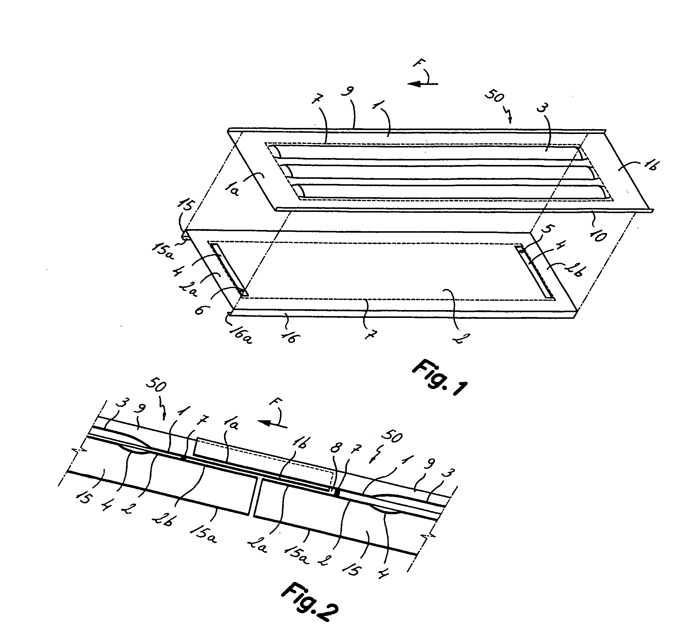
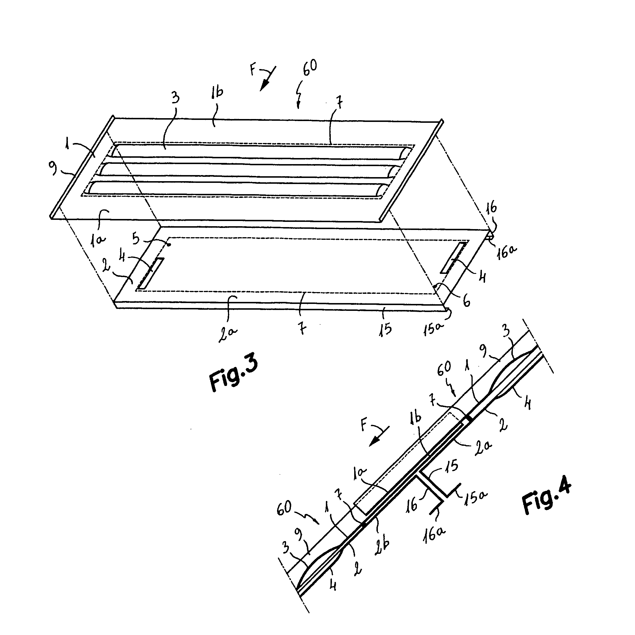
[0037] First referring to FIG. 1, reference numeral 50 generally refers to a modular solar energy-collecting enclosure element for buildings, applicable to both roofs and façades in accordance with an exemplary embodiment of the first aspect of this invention. The mentioned modular solar energy-collecting enclosure element 50, in its most elementary version, comprises an outer plate 1 and an inner plate 2, facing each other and joined together by at least one leak-tight joint line 7 along the length of a closed perimeter. In FIG. 1, the position of this leak-tight joint line 7, which can be obtained, for example, by a continuous roll welded bead, is shown as dotted lines 7 in relation to outer plate 1 and inner plate 2. In the shown exemplary embodiment, the outer plate 1 includes, within the perimeter defined by the leak-tight joint line 7 some conformations 3 that define three slightly concave channels on the inner side of the outer plate 1, which run parallel to the longitudinal ...


PUM


Abstract

A solar energy-collecting modular element for enclosure, and modular system for forming solar energy-collecting enclosures in buildings is described. The modular solar energy-collecting enclosure element comprises an outer plate and inner plate, facing each other and joined together by at least one leak-tight joint line along a closed perimeter. One or both plates include one or more hollow conformations within the perimeter that form a circuit for a heat-carrying fluid with an inlet and an outlet. The joint line is at a distance from the downstream transversal edges from the outer and inner plates thereby providing an accessible gap between respective free outer and inner portions of the outer and inner plates downstream from the joint line. This accessible gap is adapted to be plug-connected to an upstream free portion of the outer plate of a similar adjacent modular element located downstream.

Description

SCOPE OF THE INVENTION [0001] This invention relates to a modular solar energy-collecting enclosure element provided with configurations for water-tight joining to other adjacent modular elements in both longitudinal and transversal directions, in relation to the possible flow of water over them, establishing water-tight joints in order to form a façade or roof of a building. This invention also relates to a modular system for forming solar energy-collecting enclosures on buildings, applicable to façades and roofs, which includes the modular solar energy collection enclosures of the invention, together with a plurality of supplementary roof elements provided with similar configurations for their water-tight joining, together with other structural elements. PRIOR ART [0002] The use in a building of panels that perform the functions of both closing off the building and that of collecting solar heat-energy is known. [0003] The document FR-A-2345672 describes a solar energy collector co...

Claims


Application Information

Patent Timeline
IPC IPC(8): F24J2/24E04D13/18F24S10/50F24S10/70
CPCF24J2/204Y02E10/44Y02B10/20F24J2/464F24S80/40F24S10/503
Inventor GARCIA CORS, JOSEPGARCIA SANCHEZ, JOSE
Owner GARCIA CORS JOSEP
Learn More