Heat radiator

a radiator and heat sink technology, applied in the direction of cooling/ventilation/heating modification, semiconductor device details, semiconductor/solid-state device details, etc., can solve the problem of difficult to stabilize the performance the heat cannot be fully absorbed by semiconductor chips, and the cooling power of the air-cooling fin is generally lower than that of the water-cooling fin. achieve the effect of simple structure and high cooling power

Inactive Publication Date: 2007-10-04
DOWA METALTECH CO LTD
View PDF13 Cites 84 Cited by
  • Summary
  • Abstract
  • Description
  • Claims
  • Application Information

AI Technical Summary

Benefits of technology

[0012]According to the present invention, an internal cavity communicated with the outside via a through hole is formed in a metal body, and a large number of pillar portions (or columnar portions) extending between the facing two surfaces of the inside surfaces of the internal cavity are provided at intervals, so that it is possible to produce a heat radiator having a high cooling power with a simple structure without increasing the size of a conventional typical heat radiator.

Problems solved by technology

However, since an air-cooling fin is used in the method disclosed in Japanese Patent Laid-Open No. 4-363052, there are problems in that the cooling power of the air-cooling fin is generally lower than that of a water-cooling device and that it is difficult to stabilize the performance of the air-cooling fin.
Therefore, even if the water-cooling heat radiators proposed in Japanese Patent Laid-Open Nos. 62-52945, 1-63142 and 2004-247684 are used, it is not possible to fully radiate heat from semiconductor chips and so forth unless the structure of the water-cooling heat radiators is complicated and / or unless the size of the water-cooling heat radiators is increased.

Method used


Image

  • Heat radiator
  • Heat radiator
  • Heat radiator

Examples


first preferred embodiment

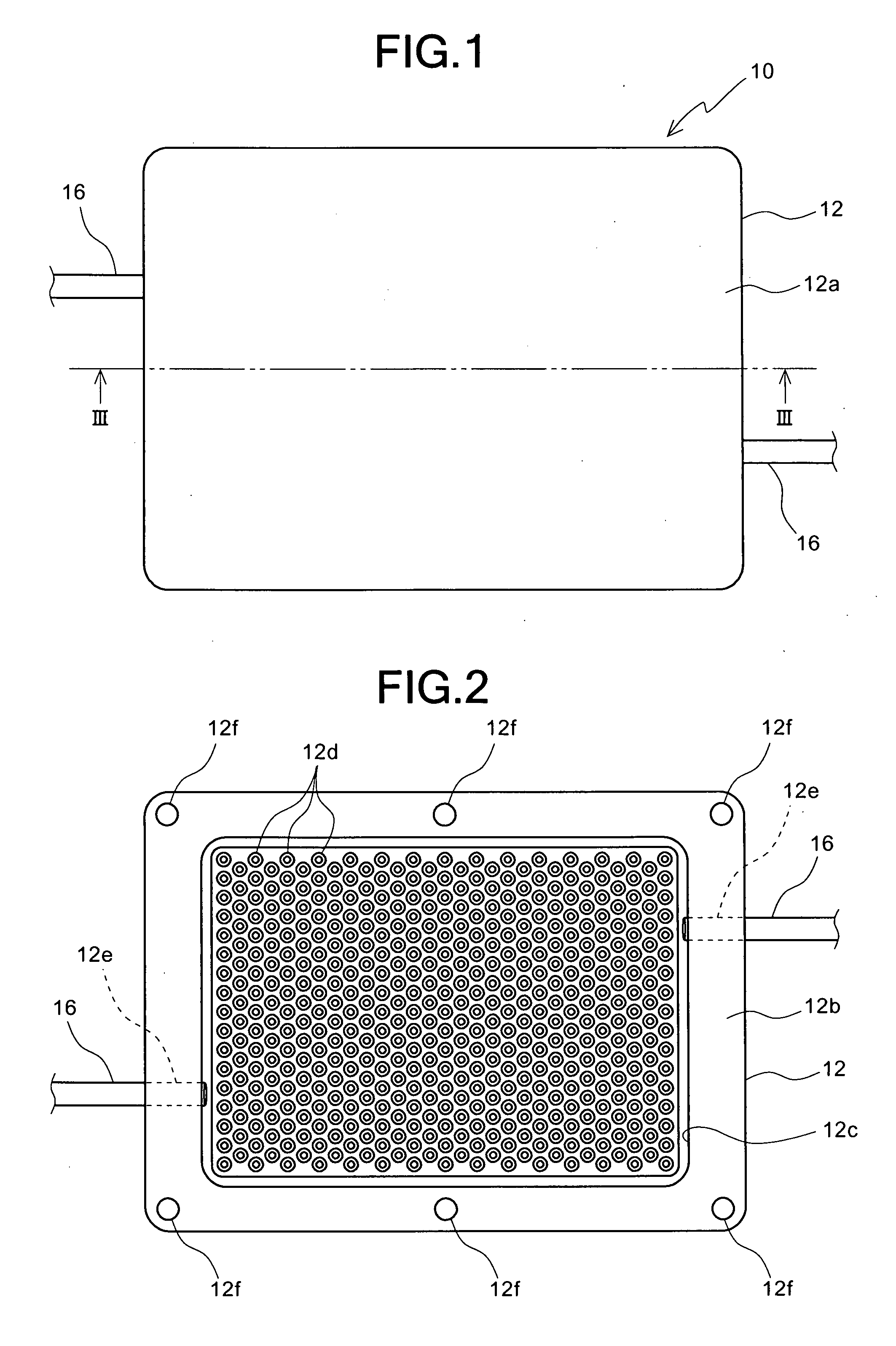
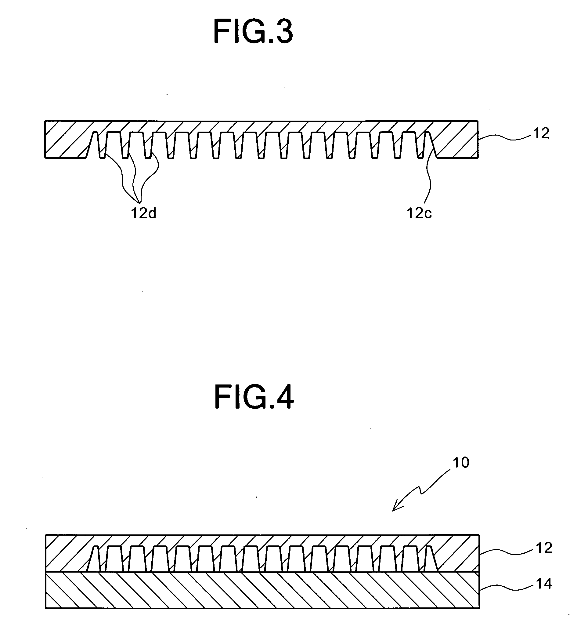
[0033]FIGS. 1 through 4 show the first preferred embodiment of a heat radiator according to the present invention. FIG. 1 is a plan view of a heat radiator in this preferred embodiment, and FIG. 2 is a bottom view of a radiating member of the heat radiator of FIG. 1 before a lid member is mounted on the radiating member. FIG. 3 is a sectional view of the radiating member of the heat radiator taken along line III-III of FIG. 1 before a lid member is mounted on the radiating member, and FIG. 4 is a sectional view of the heat radiator of FIG. 1 when a lid member is mounted on the radiating member.

[0034]As shown in these figures, the heat radiator 10 in this preferred embodiment comprises: a flat-plate-shaped radiating member (first member) 12 of a metal, such as aluminum or an aluminum alloy, the planar shape of which is a substantially rectangular shape; and a flat-plate-shaped lid member (second member) 14 of a metal, such as aluminum or an aluminum alloy, the planar shape of which i...

second preferred embodiment

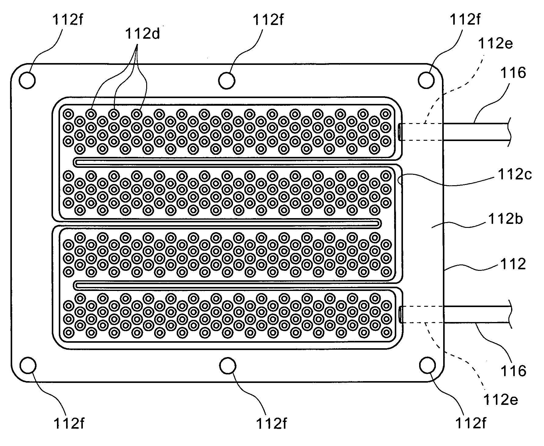
[0040]FIG. 5 shows the reverse of a radiating member of the second preferred embodiment of a heat radiator according to the present invention. The heat radiator in this preferred embodiment substantially has the same construction as that of the heat radiator 10 in the first preferred embodiment, except that a tortuously extending (or meandering or snaking) recessed portion 112c is formed by connecting four recessed portions, which extend in parallel to each other in longitudinal directions, in place of the substantially rectangular recessed portion 12c of the radiator 10 in the first preferred embodiment, and that a pair of through holes 112e pass through the peripheral portion of the radiating member 112 from both ends of the recessed portion 112c to the side face of the radiating member 112. Therefore, reference numbers in FIG. 5 are shown by adding 100 to the reference numbers given to the same structural portions as those of the heat radiator 10 in the first preferred embodiment...


PUM


Abstract

A heat radiator 10 includes: a first member 12 which has a recessed portion 12c in one side thereof and which has a large number of substantially circular truncated conical protruding portions 12d formed on the bottom face of the recessed portion 12c; and a second member which is fixed to the first member 12 on the side of the recessed portion 12c for defining an internal cavity and which contacts the tip end face of each of the large number of protruding portions 12d of the first member 12, wherein the first member 12 has a pair of through holes 12e for supplying a coolant into the internal cavity and for discharging the coolant from the internal cavity.

Description

BACKGROUND OF THE INVENTION[0001]1. Field of the Invention[0002]The present invention generally relates to a heat radiator. More specifically, the invention relates to a heat radiator used for radiating heat from a heating element to a coolant which flows therein.[0003]2. Description of the Prior Art[0004]In a conventional metal / ceramic bonding substrate used as an insulating substrate for power modules, a metal circuit plate is bonded to one side of a ceramic substrate, and a radiating metal base plate is bonded to the other side thereof, semiconductor chips and so forth being mounted on the metal circuit plate. In order to radiate heat from heating elements, such as semiconductor chips, to the outside, there is known a method for mounting a radiating fin on the reverse of a radiating base plate via a radiating grease. There is also known a method for bonding a radiating fin to a semiconductor device mounting substrate via a brazing filler metal (see, e.g., Japanese Patent Laid-Ope...

Claims


Application Information

Patent Timeline
Patent Type & Authority Applications(United States)
IPC IPC(8): H05K7/20
CPCH01L23/473H01L2924/0002H01L2924/00
Inventor TAKAHASHI, TAKAYUKI
Owner DOWA METALTECH CO LTD
Why Eureka
Try Eureka