Roller disk brake for a winch

Active Publication Date: 2007-10-04
WARN INDUSTRIES
View PDF43 Cites 8 Cited by
  • Summary
  • Abstract
  • Description
  • Claims
  • Application Information

AI Technical Summary

Benefits of technology

[0007] According to the principles of the present invention, a brake mechanism is provided having an advantageous construction. The brake mechanism includes a motor output shaft outputting a driving torque in a first and a second rotary direction. A camming device operably couples the output shaft to a drive shaft for fixed rotation. A roller clutch operably couples the drive shaft and a brake device. The brake device is normally in an engaged position that prevents rotation of the brake device. The roller clutch permits the drive shaft to spin freely relative to the brake device when the output shaft of the motor is driven in the first rotary direction, yet locks the drive shaft and brake device together when

Problems solved by technology

However, traditional brake mechanisms suffer from a number of disadvantages.
For example, traditional brake mechanisms are incapable of eliminating drag associated with the brake mechanism when the device is being driven in the power-in direction.
Similarly, traditional brake mechanisms often suffer from exces

Method used


Image

  • Roller disk brake for a winch
  • Roller disk brake for a winch
  • Roller disk brake for a winch

Examples


Embodiment Construction

[0022] The following description of the preferred embodiment is merely exemplary in nature and is in no way intended to limit the invention, its application, or uses. For example, the present invention may find utility in a wide variety of applications, such as winches, hoists, or similar device.

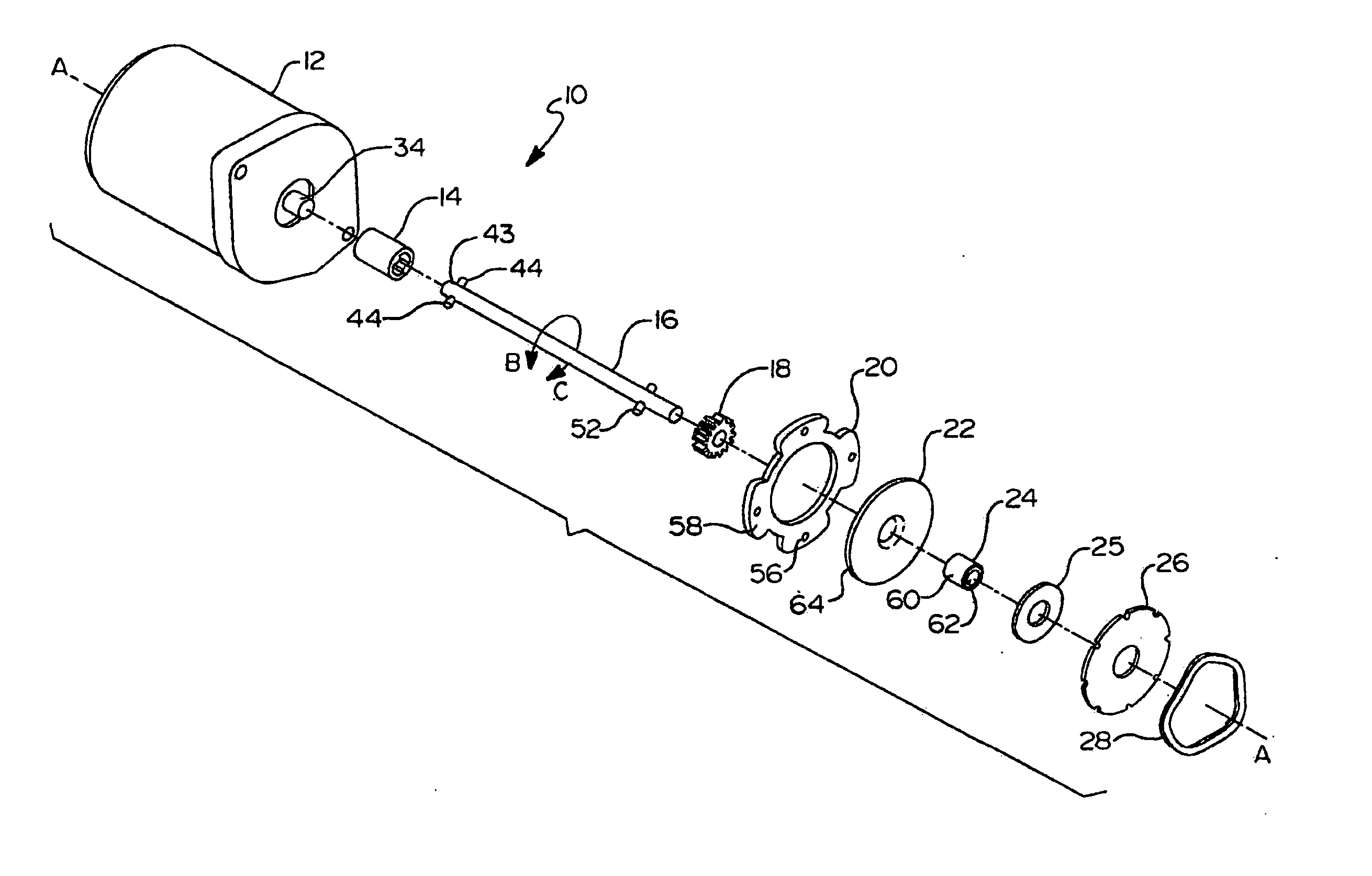
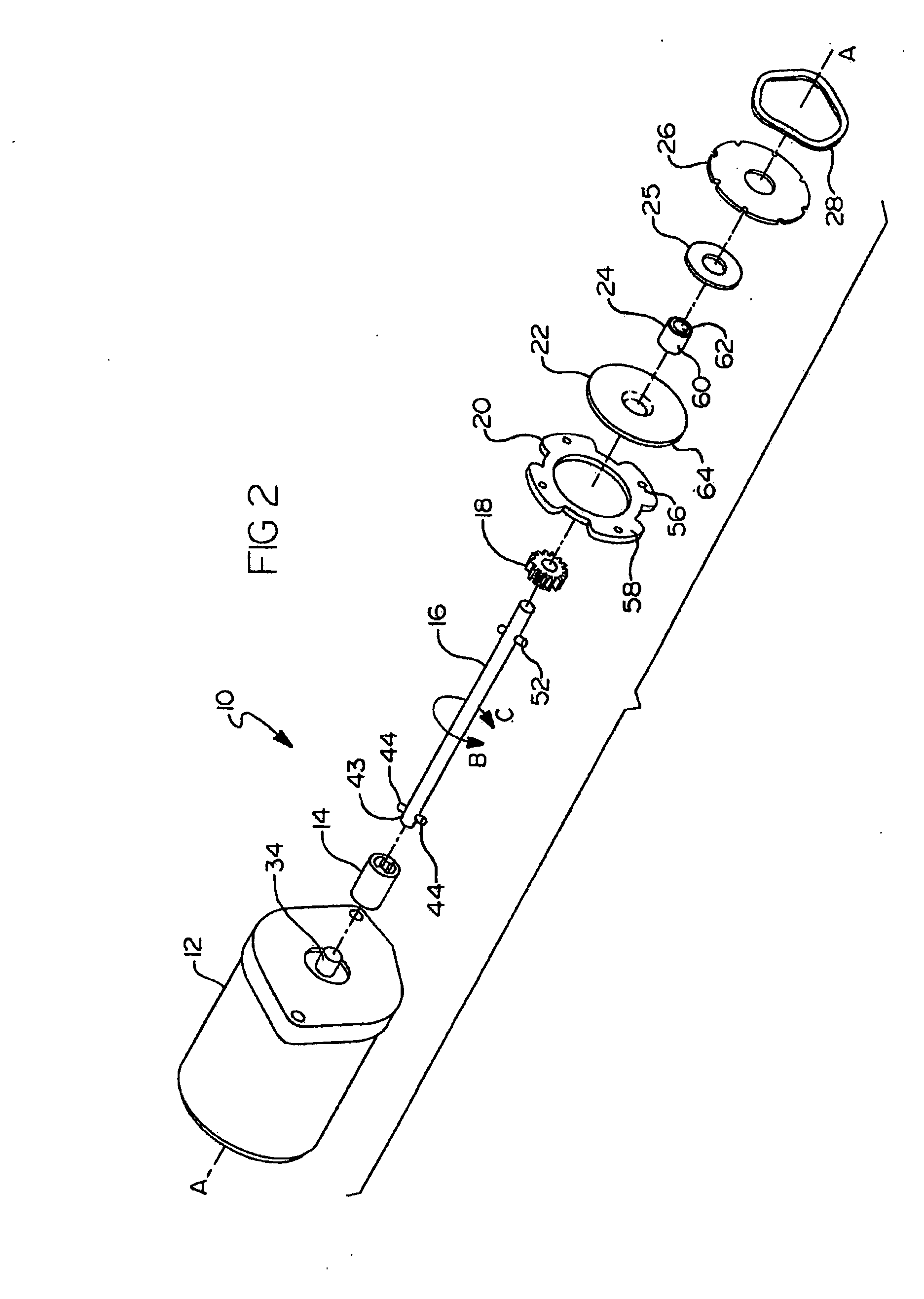
[0023] Referring now to the figures, there is illustrated a roller disk brake system, generally indicated at 10, for use with a winch, hoist, or other power device requiring resistance to driven torque. In the interest of brevity, the present disclosure will not discuss in detail the overall construction of the associated winch, hoist, or other power device.

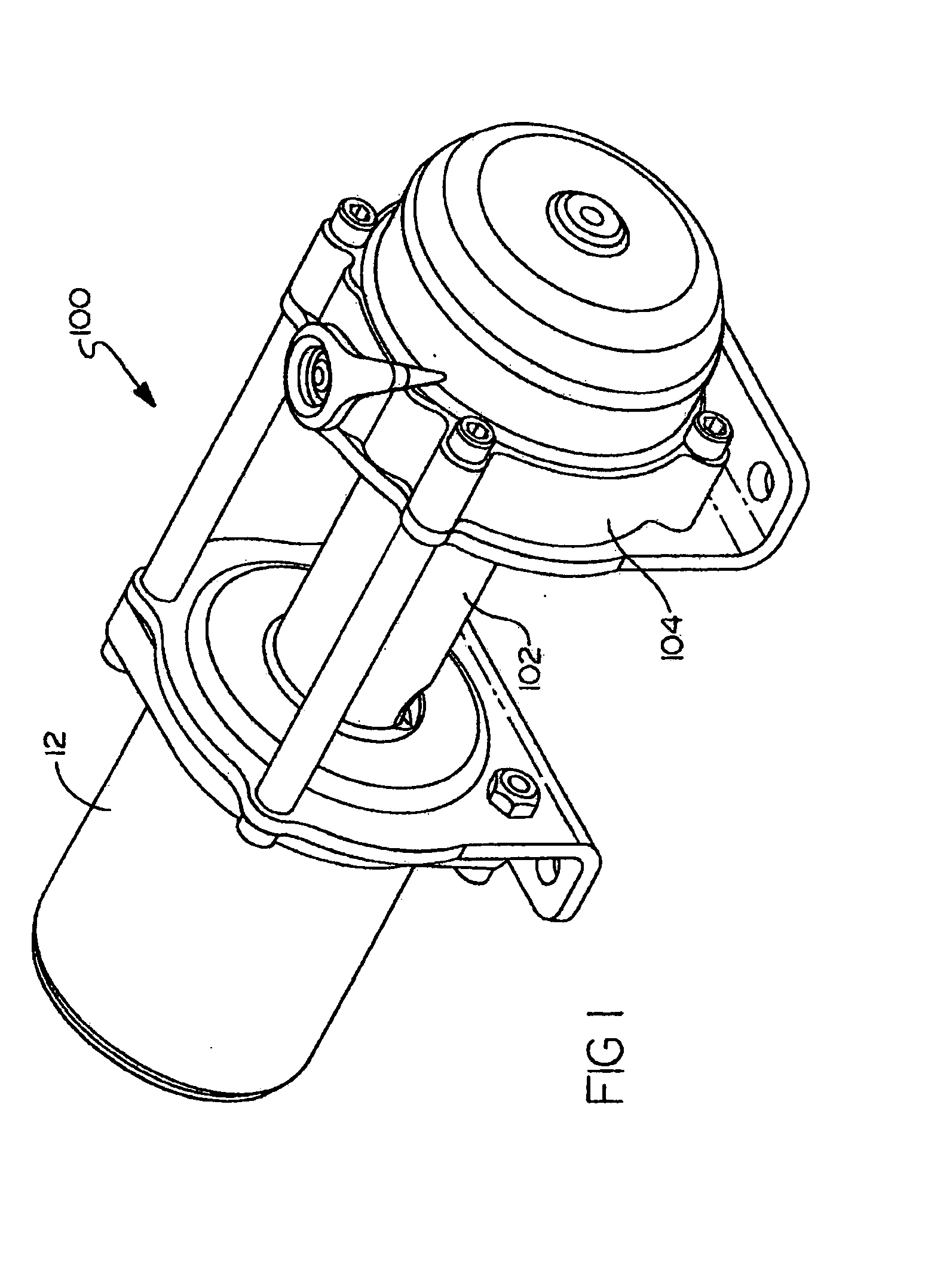
[0024] However, briefly by way of background, an exemplary winch 100 for use with the present invention is illustrated in FIG. 1. Winch 100 preferably includes a rotatable hollow cylindrical drum 102 for winding and unwinding a length of wire rope or cable (not shown). Drum 102 may be positively driven in either direction by a reversing...


PUM


Abstract

A power device includes a motor, a drive shaft, and a roller brake system including a cam mechanism. The motor may put out a driving torque in a first and a second rotary direction. The cam mechanism includes first and second cam members. The first cam member may be in a driven engagement with the motor and the second cam member may be slidably engaged with the first cam member and coupled to the drive shaft. The first cam member includes a circumferentially disposed ramped surface having a stop member at a first end thereof. The said second cam member is axially and rotatably fixed with the drive shaft and includes an axially extending protrusion disposed about a circumference thereof and slidably engaged with the ramped surface.

Description

CROSS-REFERENCE TO RELATED APPLICATIONS [0001] This application is a continuation-in-part of U.S. patent application Ser. No. 10 / 829,756 filed on Apr. 22, 2004. The disclosure of the above application is incorporated herein by reference.FIELD OF THE INVENTION [0002] The present invention relates to brake mechanisms and, more particularly, relates to a brake mechanism for use with a winch, hoist, or other device requiring resistance to driven torque. BACKGROUND OF THE INVENTION [0003] As is common practice, winches, hoists, and other power devices requiring resistance to driven torque often employ brake mechanisms to satisfy various design criteria. Winches, hoists, and the like typically employ a motor that drives a gear train, which is coupled to a drum. The motor is often capable of being driven in opposite rotary directions, which is commonly referred to as “power-in” and “power-out” directions. When the motor is not actuated (i.e. idle), it is typically preferable that the drum ...

Claims


Application Information

Patent Timeline
IPC IPC(8): B60T1/00F16D63/00F16D65/14F16D67/00
CPCF16D67/00F16D2127/005F16D2125/36B60T1/062
Inventor ELLIOTT, RONALD L.
Owner WARN INDUSTRIES
Why Eureka
Try Eureka