
Self-cleaning screen with check valve for use in shallow water pumping

a self-cleaning screen and check valve technology, which is applied in the direction of liquid fuel engines, separation processes, filtration separation, etc., can solve the problems of inability to generate sufficient vacuum in the impeller, the use of centrifugal pumps, and the inability to draw fluid for self-priming

Active Publication Date: 2007-10-04
WIETHAM ROBERT J
View PDF11 Cites 31 Cited by
  • Summary
  • Abstract
  • Description
  • Claims
  • Application Information

AI Technical Summary

Benefits of technology

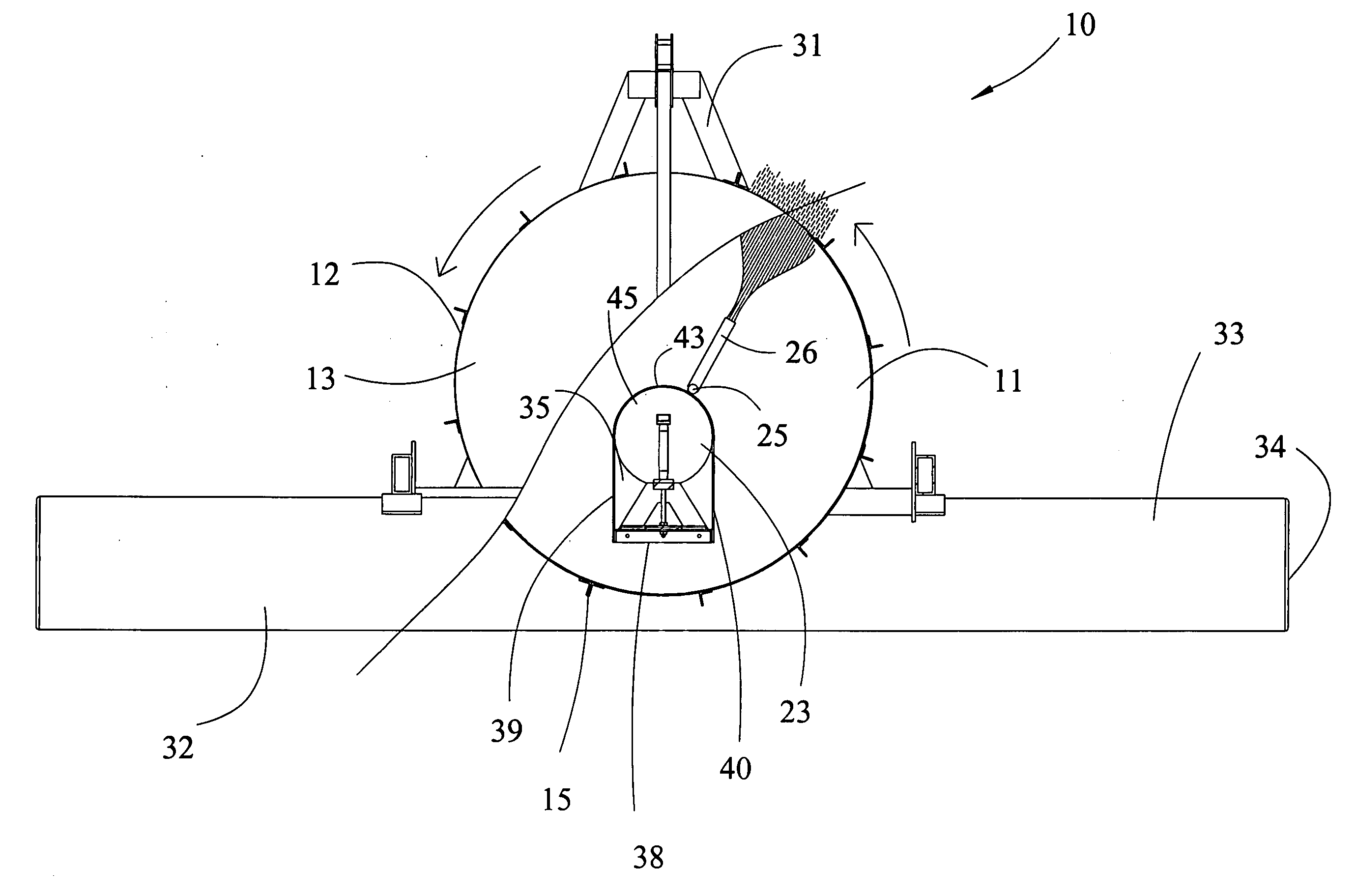
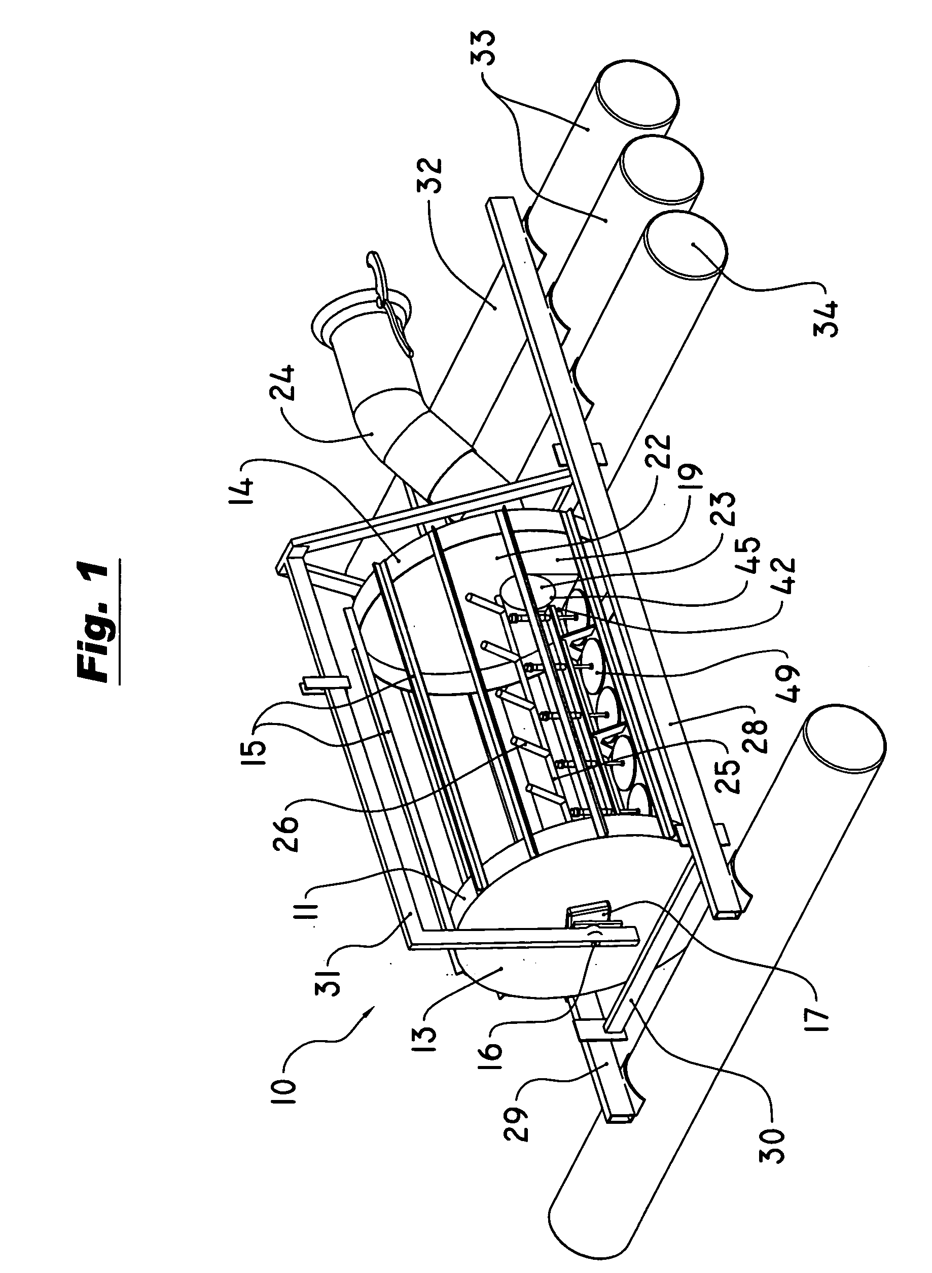
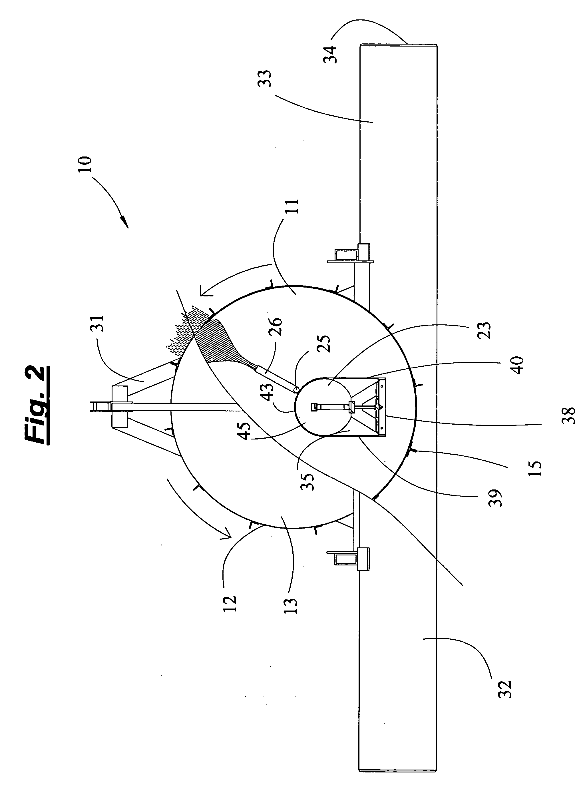
[0009] The present invention provides a self-cleaning screen for shallow water pumping. The screen includes a rotatable drum having sidewalls made of a mesh material for removing debris from water as the water passes into the drum. A suction chamber is positioned within the drum for collecting and feeding water to a suction pipe that supplies a centrifugal pump. A plurality of inlet openings are arranged across a bottom side of the suction chamber. A check valve assembly prevents water from back flowing through the inlet openings, to thereby maintain water in the suction chamber and the suction pipe to keep the pump primed when it is off. The check valve assembly includes a plurality of valve members having valve stems that are slidably mounted above the inlet openings for movement between closed and open positions. The valve members have valve faces that cover the inlet openings when the valve members are in their closed positions. The valve members are movable upwardly from their closed positions to their open positions upon movement of water through the inlet openings into the suction chamber, and return to their closed positions by force of gravity when water stops flowing into the suction chamber.
[0012] According to another broad aspect of the present invention, a pumping system is provided, comprising: a suction pipe for supplying water to a centrifugal pump; a screen for preventing debris from entering the suction pipe; and a check valve assembly positioned between the screen and the suction pipe to maintain a prime in the suction pipe when the pumping system is stopped, the check valve assembly comprising at least one valve member having a valve stem and a valve face, the valve stem being slidably received in a support structure for allowing the valve member to move between a closed position in which the valve face covers an inlet opening and an open position in which the valve face is displaced from the inlet opening.

Problems solved by technology

A well-known limitation to the use of centrifugal pumps is their limited ability to draw fluid for self-priming when starting from an air-filled or dry condition.
The impeller is typically not capable of generating a sufficient vacuum when operating in air to draw liquid up to the pump when the standing level of the liquid is below the pump.
Although self-priming centrifugal pumps have been used effectively under some conditions, they have generally suffered from a relatively greater complexity, higher expense, unreliability, and / or an inability to lift water as high as necessary to prime the pump in some applications.

Method used


Image

  • Self-cleaning screen with check valve for use in shallow water pumping
  • Self-cleaning screen with check valve for use in shallow water pumping
  • Self-cleaning screen with check valve for use in shallow water pumping

Examples


Embodiment Construction

[0027] A self-cleaning screen with a check valve assembly for use in shallow water pumping according to the present invention will now be described in detail with reference to FIGS. 1 to 12 of the accompanying drawings.

[0028] The self-cleaning screen 10 includes a rotatable drum 11 having a sidewall 12 made of a mesh material for removing debris from water as the water passes into the drum 11. The drum 11 has first and second ends 13, 14 and a plurality of slat members 15 extending along a length of the drum 11 between the first and second ends 13, 14. The first end 13 of the drum 11 is supported by a shaft 16 and bearing 17 or other suitable structure to allow the drum 11 to rotate freely about a horizontal axis during operation.

[0029] The second end 14 of the drum 11 is also supported by a support structure 18 that allows the drum 11 to rotate about the horizontal axis. The second end 14 of the drum 11 has an opening 19 through which water can be taken from the interior of the d...


PUM

PropertyMeasurementUnit
Gravityaaaaaaaaaa

Abstract

A self-cleaning screen for shallow water pumping includes a rotatable drum made of mesh material for removing debris from water passing into the drum, and a suction chamber within the drum for feeding water to a suction pipe connected to a centrifugal pump. Inlet openings are arranged across a bottom side of the suction chamber. A check valve assembly is provided to prevent water from back flowing through the inlet openings, to thereby maintain a prime in the suction pipe when the pump is off. The check valve assembly includes valve members that are slidably mounted above the inlet openings for movement between closed and open positions. The valve members move upwardly from their closed positions to their open positions upon movement of water through the inlet openings into the suction chamber, and return to their closed positions by force of gravity when water stops flowing into the suction chamber.

Description

BACKGROUND OF THE INVENTION [0001] 1. Field of the Invention [0002] The present invention relates generally to self-cleaning screen assemblies for use in shallow water pumping systems. In particular, the present invention relates to a check valve assembly for use with a self-cleaning screen in a shallow water pumping system to maintain a prime in a centrifugal pump. [0003] 2. Description of the Related Art [0004] Centrifugal pumps are commonly used to suck water out of outdoor pits, reservoirs, streams, rivers, ponds, and the like, especially for irrigation purposes. A suction pipe or hose typically extends between the water source and the centrifugal pump for supplying water to the pump. A screen is typically used to prevent debris, sand and other objects from being sucked into the suction pipe or hose and into the pump while pumping. [0005] Self-cleaning screens have been developed to prevent plugging by debris being drawn to the screen during pumping. An example of a self-cleanin...

Claims


Application Information

Patent Timeline
IPC IPC(8): B01D21/30
CPCB01D33/073F04D9/008F04D13/066F04D29/708B01D33/50Y10T137/7722
Inventor WIETHAM, ROBERT J.
Owner WIETHAM ROBERT J
Learn More