Method of manufacturing metallic foam based heat exchanger

a heat exchanger and foam technology, applied in the field of heat exchangers and manufacturing methods, can solve the problems of increasing the size of the heat exchanger unit and its accompanying plumbing system, increasing the weight and complexity of the work machine, and limitations of known designs

Inactive Publication Date: 2007-10-04
CATERPILLAR INC
View PDF4 Cites 23 Cited by
  • Summary
  • Abstract
  • Description
  • Claims
  • Application Information

AI Technical Summary

Benefits of technology

[0013] In still another aspect, the present disclosure provides a method of cooling oil in an internal combustion engine system, including the step of passing high temperature oil through an aluminum foam disposed within a first fluid passage in a first housing portion of a heat exchanger. The method further includes the s

Problems solved by technology

While many of these heat exchangers serve vital functions for the engine system, the heat exchanger units and their accompanying plumbing systems can add significant weight and complexity to the work machine.
While bar and plate style heat exchangers have enjoyed a long and successful history in the internal combustion engine arts, there are limitations to known designs, now increasingly apparent in light of the new challenges facing heat exchanger designers.
Increasing heat exchanger size is often not a viable option, as it can add weight to the overall system, and because spatial and packaging constraints may limit heat exchanger size.
While increasing fin density works up to a point, additional fins can reduce the attainable flow rate or pressure for fluids through the heat exchanger to a point that an unacceptable fluid pressure drop across the heat exchanger occurs.
While Toonen discloses a design purportedly suited to certain applications, in pa

Method used


Image

  • Method of manufacturing metallic foam based heat exchanger
  • Method of manufacturing metallic foam based heat exchanger
  • Method of manufacturing metallic foam based heat exchanger

Examples


Embodiment Construction

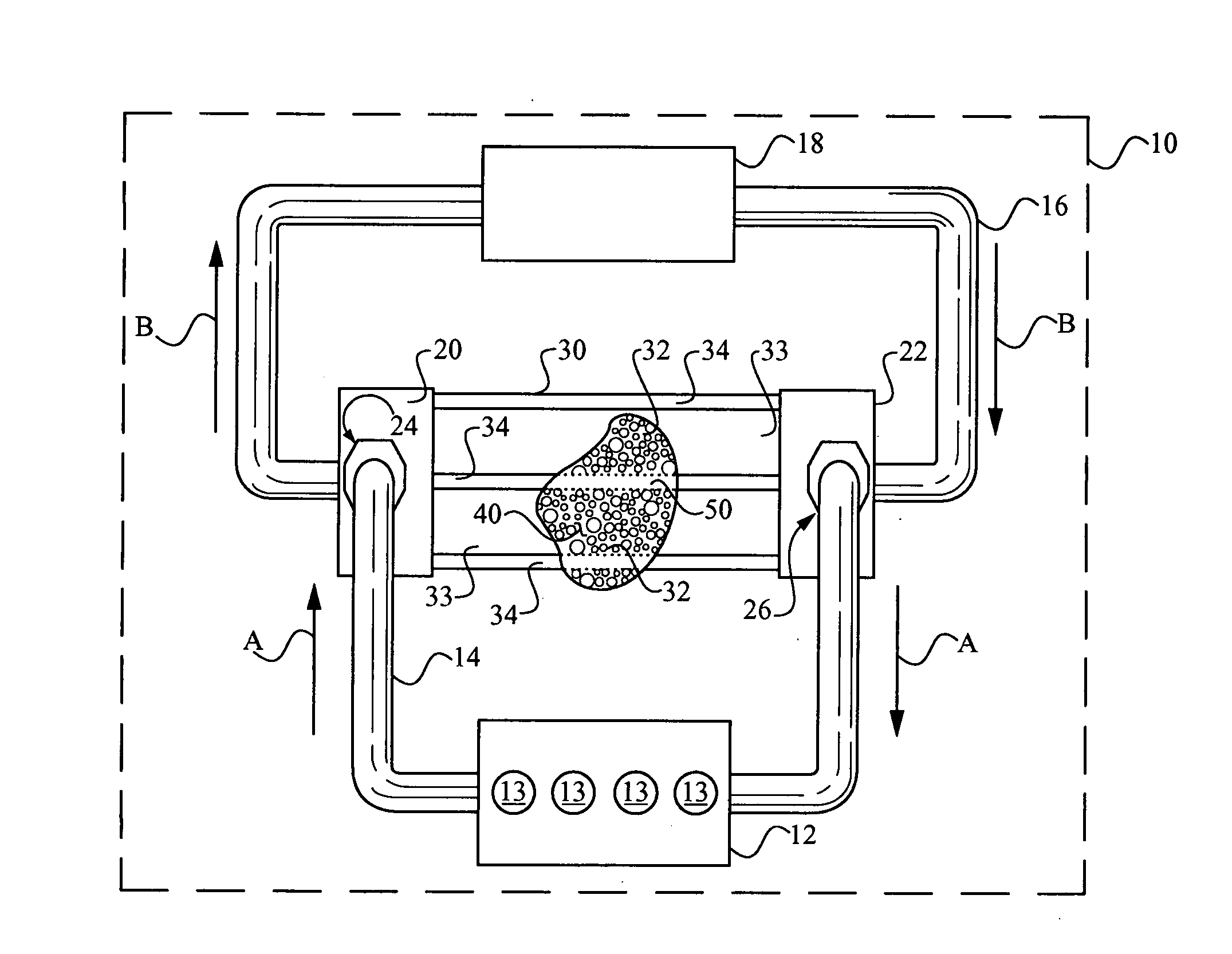
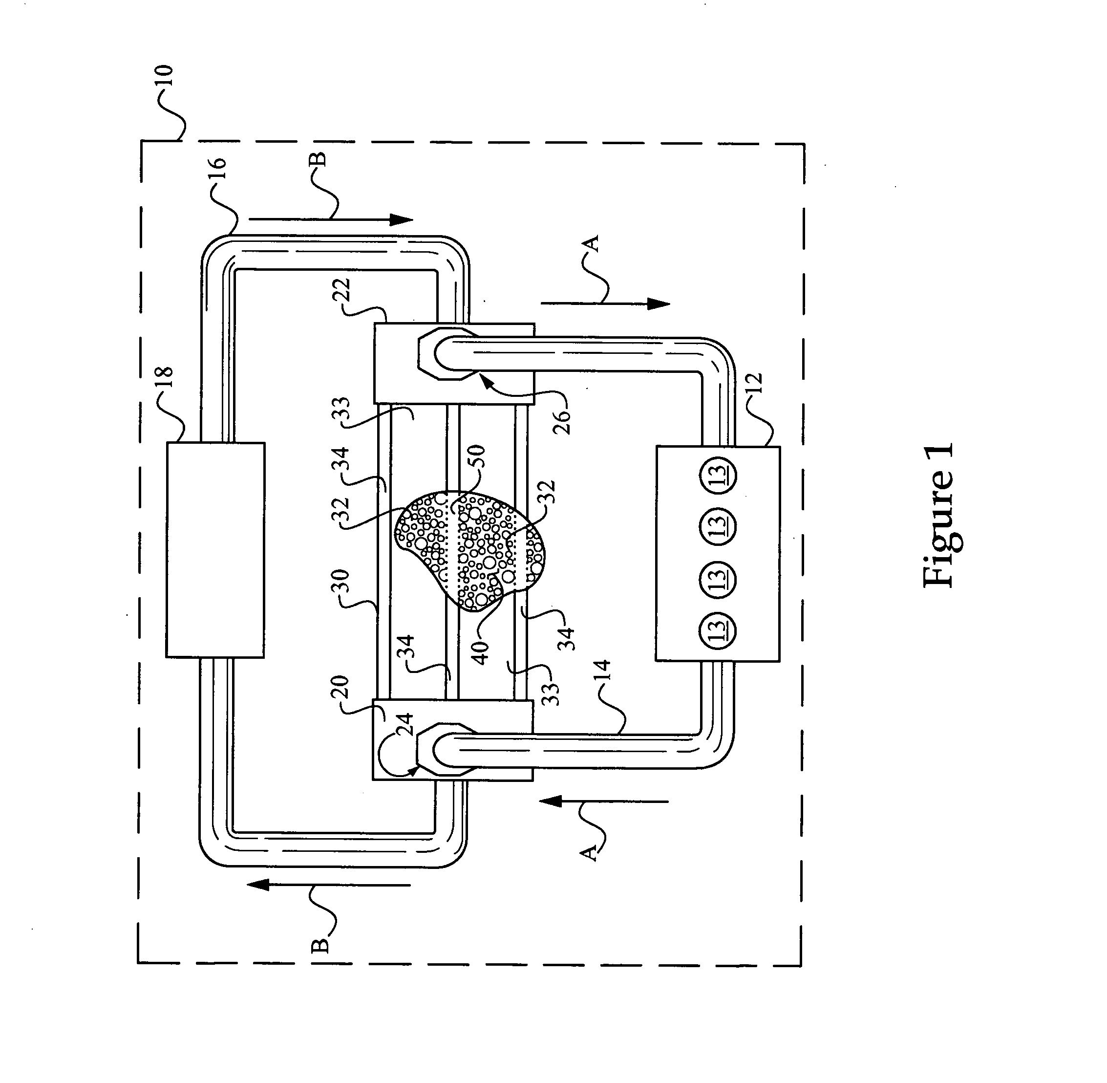
[0017] Referring to FIG. 1, there is shown an engine system 10 according to one embodiment of the present disclosure. Engine system 10 includes an engine 12 such as an internal combustion engine having a plurality of cylinders 13. Engine 12 may comprise a compression ignition engine or a spark ignited engine, for example, or another engine type. It is contemplated that engine system 10 may be mounted in a mobile work machine, such as an off-highway work machine, or it might be a stand alone engine system such as the type used in electrical power generation, or still another type of engine system. An oil conduit 14 connects with engine 12 and is configured to circulate engine cooling oil in a conventional manner. Engine system 10 further includes a radiator 18 coupled with an engine coolant conduit 16. Arrows A illustrate a direction of engine oil flow, whereas Arrows B indicate a flow of engine coolant in a direction opposite to oil flow. In other embodiments, coolant and oil might ...


PUM

PropertyMeasurementUnit
Temperatureaaaaaaaaaa

Abstract

A method of manufacturing a metallic foam based heat exchanger includes positioning an aluminum foam block, for example, within a housing defining a first fluid passage, and placing the block in contact with a second portion of the housing defining at least one other fluid passage, the second housing portion being an extrusion. A brazing flux material and a brazing filler are applied to at least one of the foam and the extrusion, the foam being thermally coupled to the extrusion with the brazing filler via heating in a brazing furnace. A heat exchanger includes a housing having a fluid passage with a metallic foam such as an aluminum foam therein. The metallic foam is attached to a metallic extrusion such as an aluminum extrusion, and connected therewith via a thermally conducting brazing filler. A method of cooling oil in an internal combustion engine is further provided, including the step of passing high temperature oil through an aluminum foam in a fluid passage of a first housing portion, and passing low temperature fluid through a second passage in a second housing portion. Heat is exchanged between the high temperature oil and the low temperature fluid at least in part via a thermally conducting attachment material joining the aluminum foam with the second portion of the housing.

Description

TECHNICAL FIELD [0001] The present disclosure relates generally to heat exchangers and manufacturing methods therefor, and relates more particularly to a method of manufacturing a metallic foam based heat exchanger for use as an oil cooler in an internal combustion engine system. BACKGROUND [0002] Heat exchangers are used in a variety of applications in modern engine systems. Internal combustion engine radiators, turbocharger intercoolers and exhaust aftercoolers are examples of heat exchangers. In addition, heat exchangers may be used to control the temperature of engine oil, transmission fluid and even air supplied to the engine or used in temperature control of an operator cabin in a work machine. [0003] Many work machines, including off-highway work machines and on-highway trucks, for example, utilize a variety of different heat exchangers coupled with their respective engine systems. Certain heat exchangers such as oil coolers are commonly coupled with the engine coolant fluid ...

Claims


Application Information

Patent Timeline
IPC IPC(8): B23K31/02
CPCF28D9/0081F28F2255/16F28F13/003
Inventor DUPREE, RONALD L.CALLAS, JAMES J.TRETHEWEY, JEREMY S.
Owner CATERPILLAR INC
Why Eureka
Try Eureka