Wave coil spring

Inactive Publication Date: 2007-10-04
PIOLAX CO LTD
View PDF12 Cites 9 Cited by
  • Summary
  • Abstract
  • Description
  • Claims
  • Application Information

AI Technical Summary

Benefits of technology

[0012]The invention was made in view of these situations, and an object thereof is to provide a wave coil spring which can be manufactured easily and moreover which can prevent the circumferential slide (buckling) so as to maintain a good load bearing performance.
[0017]In the first aspect of the invention, the component of force attempting to slide the spring main body in the direction in which the spring main body is wound spirally which is produced in the first contact portion and the component of force attempting to slide the spring main body in the direction in which the spring main body is unwound spirally which is produced in the second contact portion are caused to cancel each other out, so as to control the circumferential slide (buckling) of the spring main body. Moreover, the wave coil spring of the invention can be manufactured easily by adjusting the positions where the first contact portion and the second contact portions are formed without adding a specific working step.
[0018]For example, in the second aspect of the invention, the wave coil spring can easily be manufactured by only adjusting the contact positions of the valley portions on the n+1th coil relative to the peak portions on the nth coil.
[0019]In addition, according to the third aspect of the invention, the wave coil spring can easily be manufactured by only adjusting the pitches of the wave-like shapes.
[0020]In addition, in the fourth aspect of the invention, although the condition is produced in which the tangential component of force which is produced in each contact portion increases with application of compressive load to facilitate the occurrence of the slide (buckling), since the tangential component of force that is produced in the first contact portion and the tangential component of force that is produced in the second contact portion cancel each other out, the circumferential side (buckling) of the spring main body can be prevented in an ensured fashion even under such a condition.
[0021]As has been described heretofore, according to the invention, the wave coil spring can be provided which can easily be manufactured and moreover which can maintain a good load bearing performance while preventing the circumferential slide (buckling) of the spring main body.

Problems solved by technology

These configurations have caused problems of an increased number of working man hours and a complex manufacturing process.

Method used


Image

  • Wave coil spring
  • Wave coil spring
  • Wave coil spring

Examples


Embodiment Construction

[0030]Hereinafter, an embodiment of the invention will be described in detail by reference to the accompanying drawings.

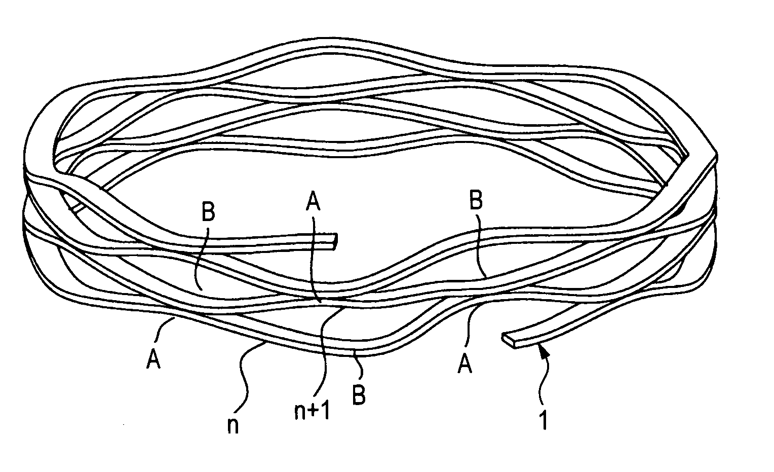
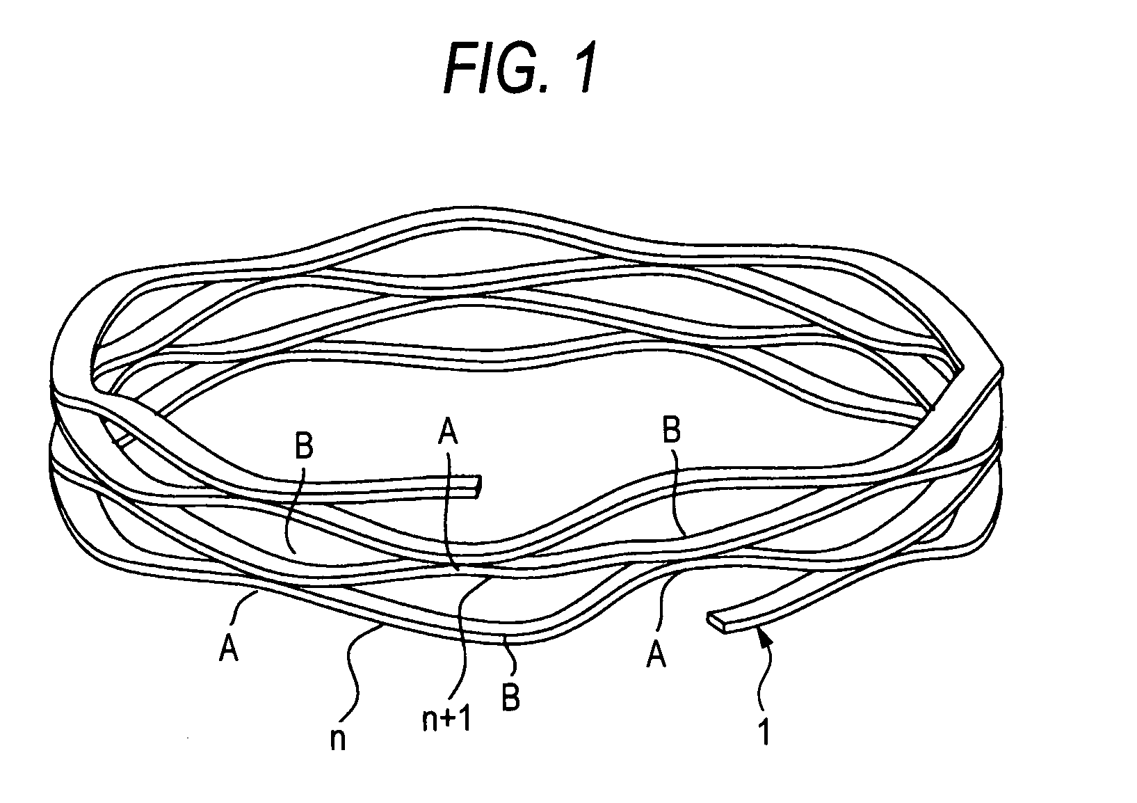
[0031]FIG. 1 is a perspective view showing an overall configuration of a wave coil spring according to an embodiment.

[0032]As is shown in FIG. 1, in a wave coil spring, a spring main body 1 is made by working a strip of spring material into a wave-like shape and winding the wave-shaped spring material in a spiral fashion. This spring main body 1 is such that peak portions A and valley portions B are formed to occur in an alternate fashion by working the spring material into the wave-like shape and is adjusted such that peak portions A on an nth coil (lower coil) face valley portions B on an n+1th coil (upper coil). Note that in this specification, n denotes a natural number.

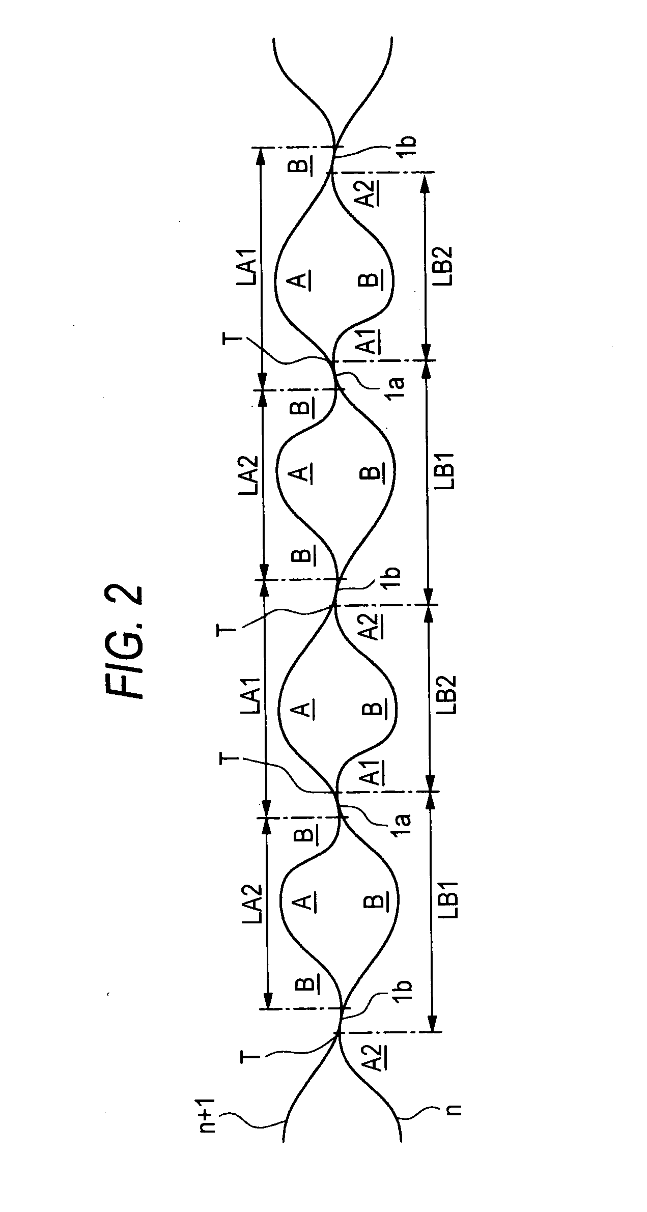
[0033]FIG. 2 is a diagram which shows exemplarily a state in which the vertically adjacent nth coil and n+1th coil of the wave coil spring of the embodiment are developed in a straight-line fash...


PUM


Abstract

A wave coil spring includes: a spring main body which has a spiral structure of a wave-shaped spring material, the spring main body bearing an axial compressive load in such a state that surfaces of the spring main body which face each other are brought into contact with each other at a plurality of contact portions, the plurality of contact portions including: a first contact portion where a component of force is produced with application of the compressive load, which attempts to cause the spring main body to slide in a direction in which the coil main body is wound spirally; and a second contact portion where a component of force is produced with application of the compressive load, which attempts to cause the spring main body to slide in a direction in which the spring main body is unwound spirally.

Description

BACKGROUND OF THE INVENTION[0001]1. Field of the Invention[0002]The present invention relates to a wave coil spring which is installed in, for example, a clutch system of an automatic transmission which is an automotive part.[0003]2. Description of the Related Art[0004]Wave coil springs are made by working a strip of spring material into a wave-like shape and winding the wave-shaped spring material in a spiral fashion and are in general widely used as a return spring for a hydraulic piston incorporated in a clutch system of an automatic transmission or as a damping spring in various types of equipment. As a wave coil spring of this type, there is a wave coil spring which is disclosed in JP-A-2002-174282.[0005]FIGS. 7A and 7B are diagrams which explains a problem inherent in a conventional wave coil spring. The figure exemplarily shows vertically adjacent nth coil and n+1th coil of a wave coil spring which are developed in a straight-line fashion. FIG. 7A shows a state in which no co...

Claims


Application Information

Patent Timeline
IPC IPC(8): F16F1/06
CPCF16F1/328F16F1/06F16F1/025F16F1/00
Inventor SUZUKI, HIROYUKI
Owner PIOLAX CO LTD
Why Eureka
Try Eureka