Wind energy plant with a steerable kite

a wind energy plant and kite technology, applied in the direction of electric generator control, machines/engines, mechanical equipment, etc., can solve the problems of cyclical switching of the system between the generation and consumption of electrical energy, the inability to feed any electrical energy generated into public or private grids, and the inability to achieve an economical degree of efficiency

Active Publication Date: 2007-10-04
SKYSAILS GMBH & CO KG
View PDF15 Cites 59 Cited by
  • Summary
  • Abstract
  • Description
  • Claims
  • Application Information

AI Technical Summary

Benefits of technology

[0007] In accordance with preferred embodiments, the present invention reduces at least one of the problems of the notorious device and provides an improved device in terms of both economy and energy efficiency.

Problems solved by technology

This principle has a number of disadvantages which render its practical implementation difficult and which make it difficult to achieve an economical degree of efficiency.
A first disadvantage is that cyclical switching of the system between the generation and consumption of electrical energy occurs due to the cyclical manner of operation.
On the one hand, this can cause variations which render it impossible to feed any electrical energy generated into public or private grids, for example.
Another disadvantage of this cyclical switching is that the system routinely and repeatedly transitions from commencement of veering-out to a constant veering-out operation.
Owing to these factors, it is impossible to adjust the generator in an economical manner to the convertible energy from the wind-engaging member.
As a result, the efficiency of the system is reduced and the production costs of the system are increased.
Another disadvantage of the system is that economical operation is only possible when the length of guy cable veered out is large.
However, this means large rope weights, which reduce the efficiency of the system.
The large veered-out section of load cable also generates heavy wear of the guy cable, which results in overall deterioration in the efficiency of the system.

Method used


Image

  • Wind energy plant with a steerable kite
  • Wind energy plant with a steerable kite
  • Wind energy plant with a steerable kite

Examples


Embodiment Construction

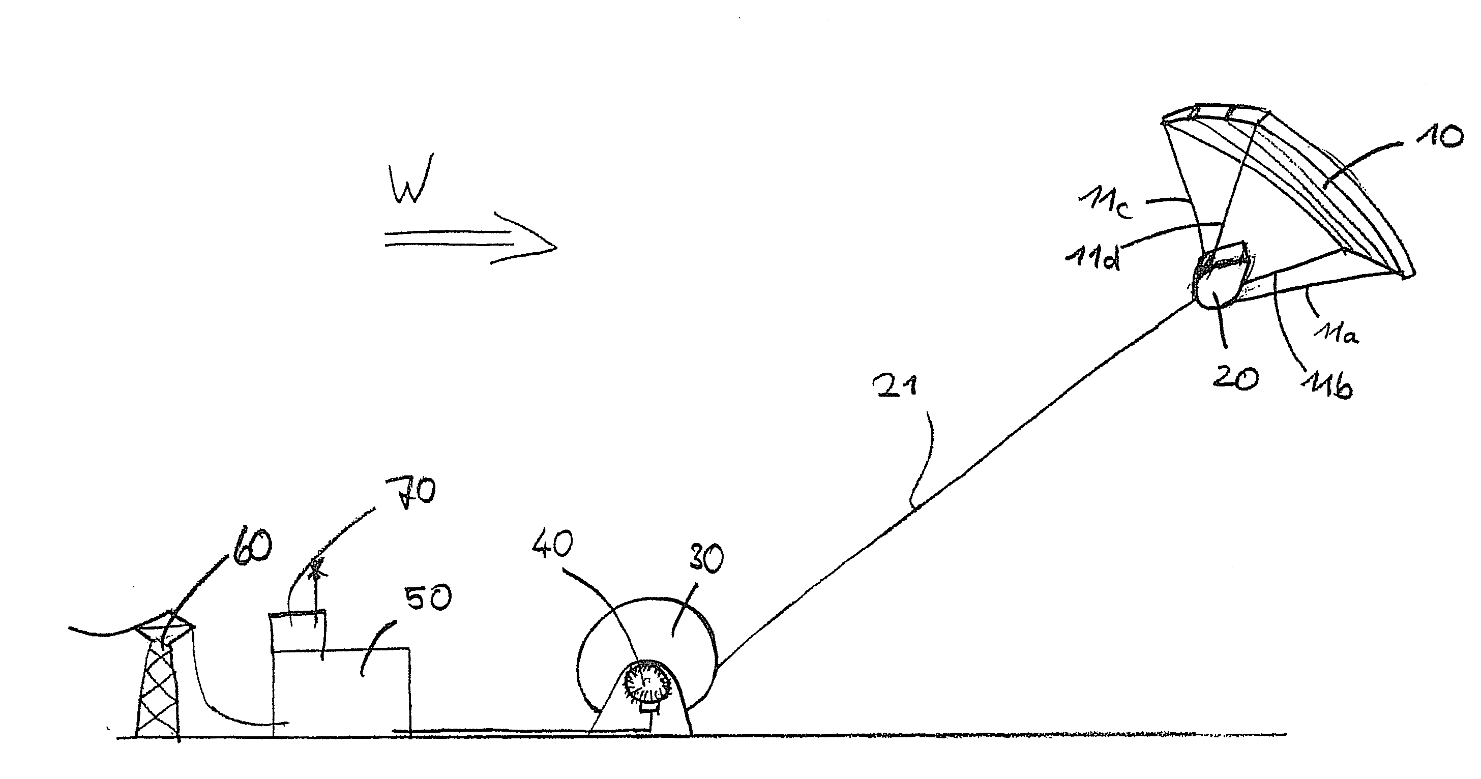
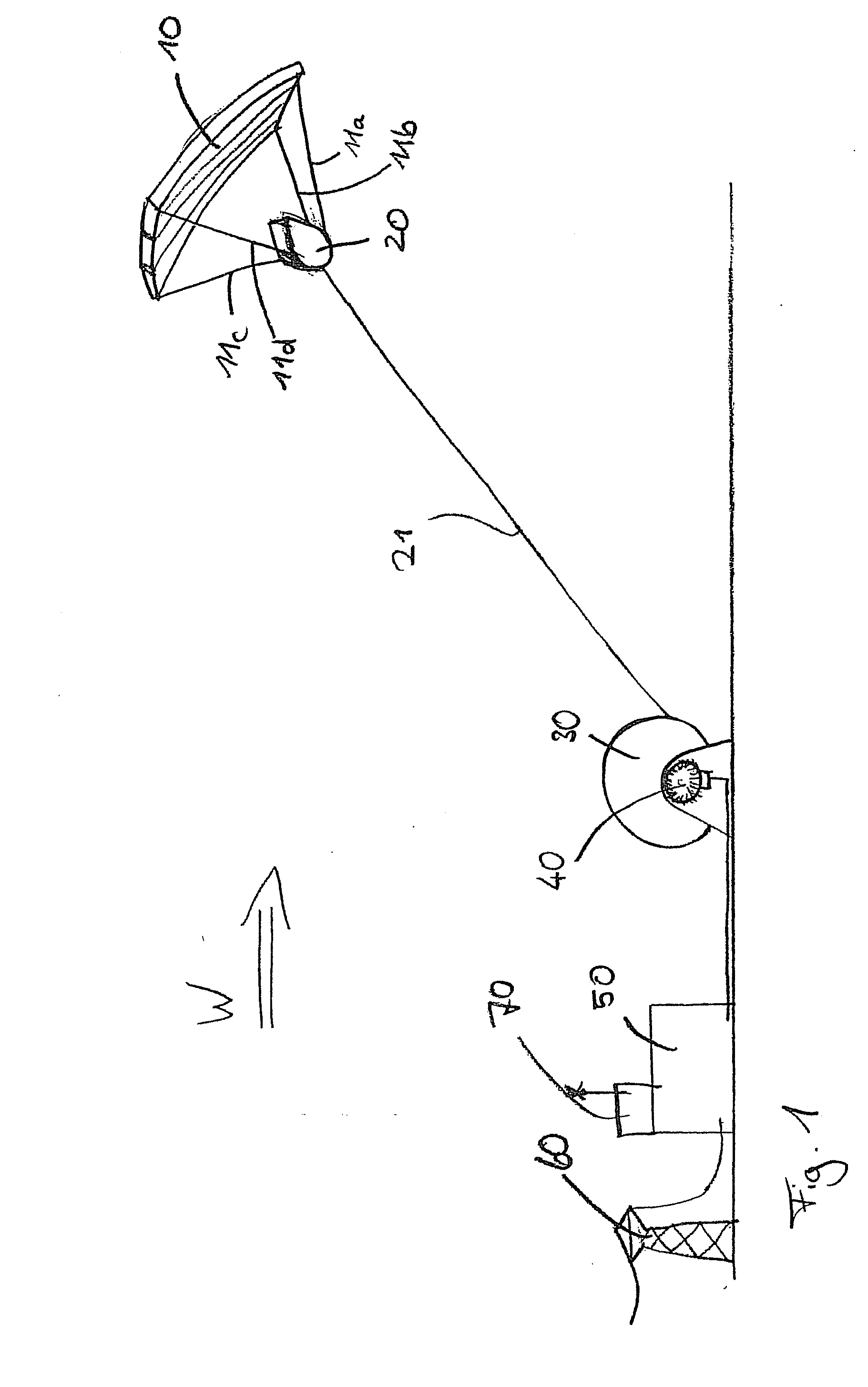
[0057]FIG. 1 shows a steerable kite 10 which is fixed to a steering mechanism 20 by a plurality of control cables 11a-d. Steering mechanism 20 is connected by means of a load cable 21 to a winch 30 anchored to the ground.

[0058] A prime mover 40 which can be toggled between a generator and a motor function is connected to cable winch 30. The generator / motor 40 is connected to a device 50 for smoothing the generated energy and / or for intermediate storage of the generated energy, and which is connected to a public network 60 for feeding the energy obtained into said network.

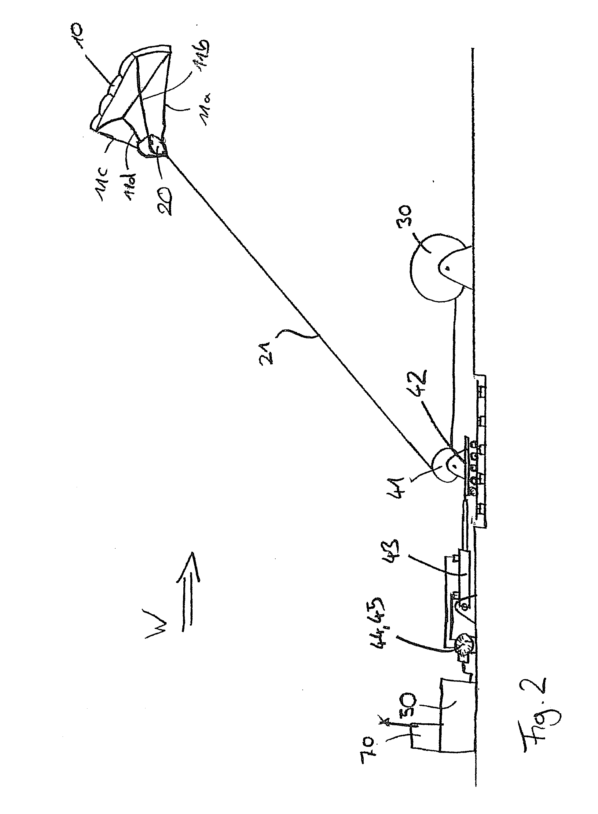
[0059]FIG. 2 shows a second embodiment of the device according to the invention. Here again, a steerable kite 10 is coupled by means of control cables 11a-d to a steering mechanism 20 which is connected for its part to a ground station by a load cable 21. The load cable 21 coming from kite 10 is deflected via a guide pulley 41 into a horizontal attitude and led to a cable winch 30.

[0060] Guide pulley 41 is mounte...


PUM


Abstract

The present invention provides a device for converting wind flow energy into mechanical energy, comprising a wind-engaging member having an aerodynamic profile which generates an uplift force in the direction of a load cable when the airflow direction is perpendicular to the load cable, a steering mechanism configured to produce a steered movement about a first axis or in a first direction of the wind-engaging member and about a second axis or in a second direction that is different from the first direction or axis of the wind-engaging member, relative to the airflow direction, and a control unit configured to use the steering mechanism to move the wind-engaging member along a predetermined flight path in a flight plane perpendicular to the load cable. The present invention further provides a method for converting wind flow energy into mechanical energy and a docking station for use with the device.

Description

CROSS-REFERENCE TO RELATED APPLICATIONS [0001] This patent application claims priority to German Patent Application No. 20 2006 005 389.1, filed Mar. 31, 2006, which is hereby incorporated by reference. BACKGROUND OF THE INVENTION [0002] The invention relates to a device for converting wind flow energy into mechanical energy, comprising a wind-engaging member connected to a base station by a load cable, a load cable storage means disposed at the base station, said storage means being configured to accommodate a section of the load cable, a control unit configured to veer out and haul in the load cable section cyclically from / into the load cable storage means, an energy converter configured to convert the energy from the wind flow force transferred from the wind-engaging member via the load cable, and the movement of the load cable section veered out from the load cable storage means into an electrical, thermodynamic or mechanical form of energy, a steering mechanism configured to pr...

Claims


Application Information

Patent Timeline
Patent Type & Authority Applications(United States)
IPC IPC(8): F03D9/00H02P9/04
CPCF03D5/00Y02E10/70F05B2240/921Y02P80/10
Inventor WRAGE, STEPHANBRABECK, STEPHAN
Owner SKYSAILS GMBH & CO KG
Why Eureka
Try Eureka