Optical Device for Measuring the Displacement Velocity of a First Moving Element with Respect to a Second Element

a technology of optical devices and moving elements, applied in the direction of devices using optical means, devices using time traversed, devices using reradiation, etc., can solve the problems of complex devices, low accuracy, and often subjected to errors in the measurement of transverse velocity

Inactive Publication Date: 2007-10-04
COMMISSARIAT A LENERGIE ATOMIQUE ET AUX ENERGIES ALTERNATIVES
View PDF2 Cites 9 Cited by
  • Summary
  • Abstract
  • Description
  • Claims
  • Application Information

AI Technical Summary

Benefits of technology

[0009] The object of the invention is to remedy these shortcomings and in particular to provide an optical measuring device enabling the longitudinal and transverse displacement velocity of a moving element to be determined with precision.

Problems solved by technology

However, as vehicles have a relative ground clearance that can vary greatly, this technique is often subject to error, as it does not take height variations into account.
Transverse velocity measurement is in particular greatly subject to error, as the magnification of the optical measuring device varies very greatly in such measuring devices.
However, this device is complex and not very functional, in particular if the distance variation is too large.
Moreover, it reduces the possible transverse velocity measurement range, but does not enable the correlation base to be varied for estimation of very low longitudinal velocities.
Moreover, as its illumination angle is reduced, this device presents a too small signal-to-noise ratio.

Method used


Image

  • Optical Device for Measuring the Displacement Velocity of a First Moving Element with Respect to a Second Element
  • Optical Device for Measuring the Displacement Velocity of a First Moving Element with Respect to a Second Element
  • Optical Device for Measuring the Displacement Velocity of a First Moving Element with Respect to a Second Element

Examples


Embodiment Construction

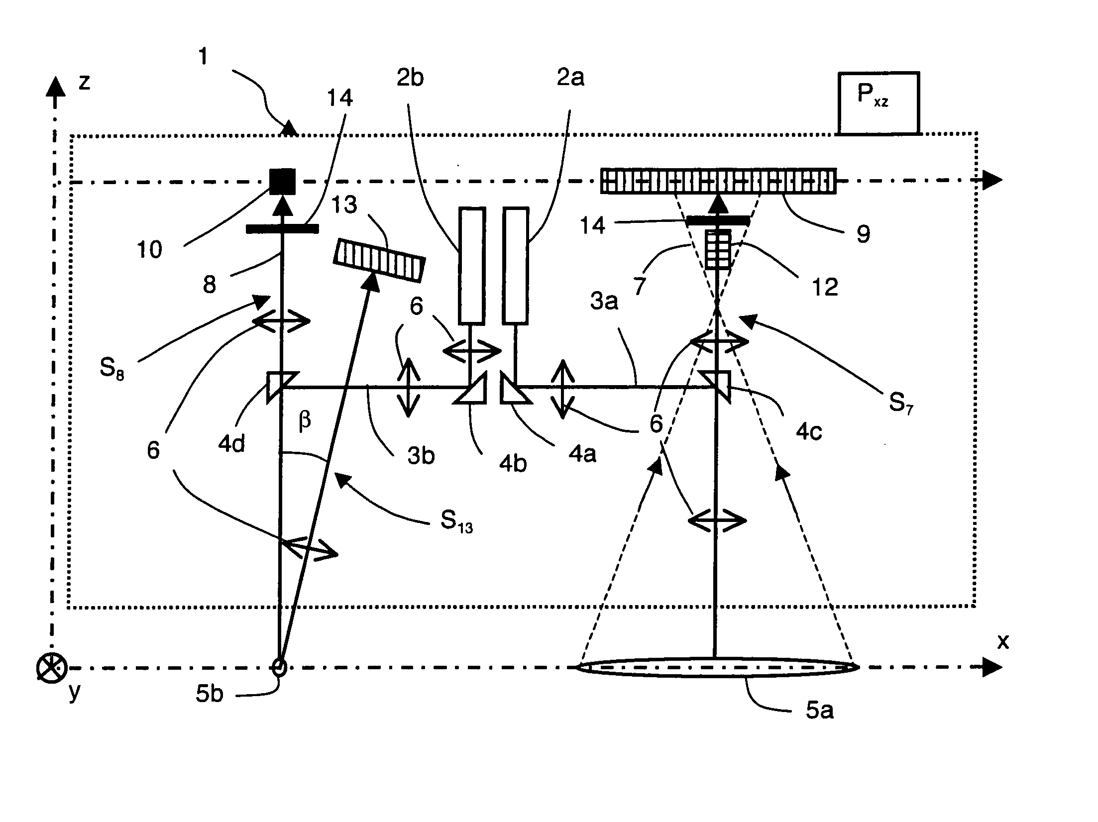
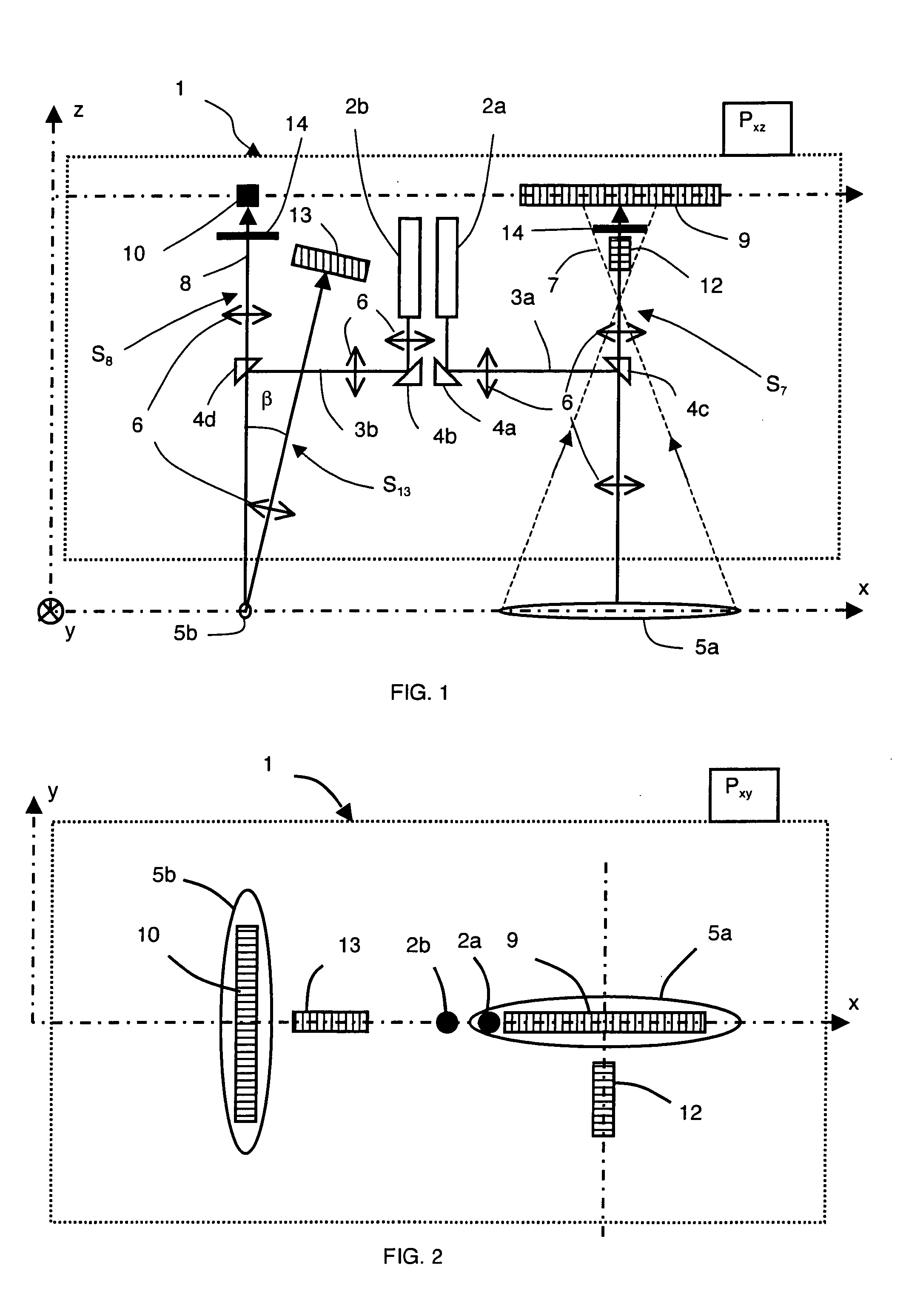
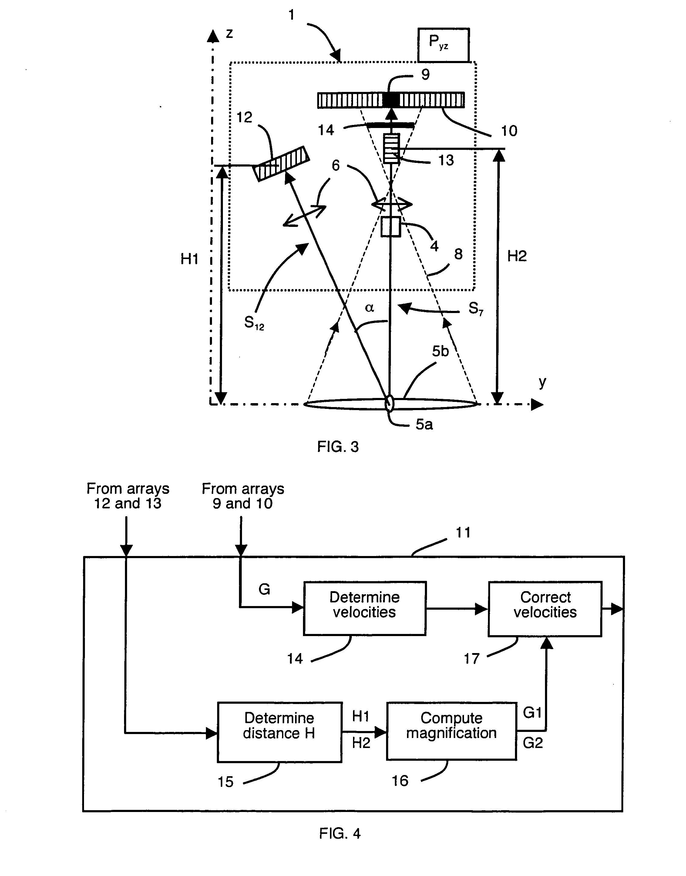
[0018] In FIGS. 1 to 3, the optical measuring device 1 is designed to measure the longitudinal displacement velocity and / or the transverse displacement velocity of a first moving element, for example a car, with respect to a second element, for example the ground. Considering a reference coordinates system x, y and z, represented in FIG. 1, the front view of the device 1, represented in FIG. 1, corresponds to the plane Pxz, the top view of the device 1, represented in FIG. 2, corresponds to the plane Pxy and the side view of the device 1, represented in FIG. 3, corresponds to the plane Pyz. The device 1 is fixed for example under the body of the car, which moves in the positive direction along the x-axis, substantially parallel to the ground.

[0019] In the particular embodiment illustrated in FIGS. 1 to 3, the device 1 comprises two lasers 2a, 2b which project two incident light beams 3a, 3b on the ground. The lasers 2a, 2b are preferably arranged in a central zone of the device 1 a...


PUM


Abstract

An optical device for measuring the displacement velocity of a first movable element in relation to a second element which is fixed to one of said elements and comprises two lasers transmitting two incident beams towards the other elements. The device including photosensitive linear arrays for front and rear detection which are substantially perpendicular to each other. Additional front and rear photosensitive linear arrays are disposed at a distance from the photosensitive front and rear linear arrays. A processing circuit is connected to the photosensitive linear arrays and determines the longitudinal and/or transversal displacement velocity of the movable element. The circuit also determines the distance between the device and the other element by means of optical triangulation and corrects the longitudinal and/or transversal displacement velocity value according of the said distance.

Description

BACKGROUND OF THE INVENTION [0001] The invention relates to an optical device for measuring the displacement velocity of a first moving element with respect to a second element, the device being fixed to one of the two elements and comprising: [0002] means for emitting at least one incident light beam in the direction of the other element, [0003] means for receiving the light scattered by the other element, comprising front and rear detection means arranged substantially perpendicularly to one another, [0004] processing means, connected to the front and rear detection means and comprising means for determining the longitudinal and / or transverse displacement velocity of the moving element. STATE OF THE ART [0005] Several measuring techniques are known for measuring the displacement velocity of a first moving element with respect to a fixed second element, in particular the longitudinal and transverse displacement velocities. [0006] The Patent FR-A-2749086 describes in particular a co...

Claims


Application Information

Patent Timeline
Patent Type & Authority Applications(United States)
IPC IPC(8): G01P3/36G01P3/80G01S17/48G01S17/58
CPCG01P3/68G01P3/806G01S17/58G01S17/48G01S7/497
Inventor CATTIN, VIVIANEPELTIE, PHILIPPEFLAMENT, BRUNOFOURCAULT, WILLIAM
Owner COMMISSARIAT A LENERGIE ATOMIQUE ET AUX ENERGIES ALTERNATIVES
Why Eureka
Try Eureka