Vision inspection system device and method

a technology of vision inspection and inspection system, which is applied in the field of machine vision inspection devices, can solve the problems of inability to accurately investigate flaws/contamination, inability to accurately detect defects, etc., and achieves the effect of greatly increasing the fabrication time and expense of composite items, and reducing the cost of inspection

Active Publication Date: 2007-10-04
THE BOEING CO
View PDF1 Cites 40 Cited by
  • Summary
  • Abstract
  • Description
  • Claims
  • Application Information

AI Technical Summary

Problems solved by technology

Deviations from this pattern may result in unacceptable wrinkles, twist, gaps and/or overlap of the courses.
Other errors that may occur during ply placement include foreign objects, such as, bits of backing material or debris (“blobs”) becoming stuck to the surface of the tool or course.
In these and other instances, if the error is not identified and corrected prior to placement of the next ply, materia

Method used


Image

  • Vision inspection system device and method
  • Vision inspection system device and method
  • Vision inspection system device and method

Examples


Embodiment Construction

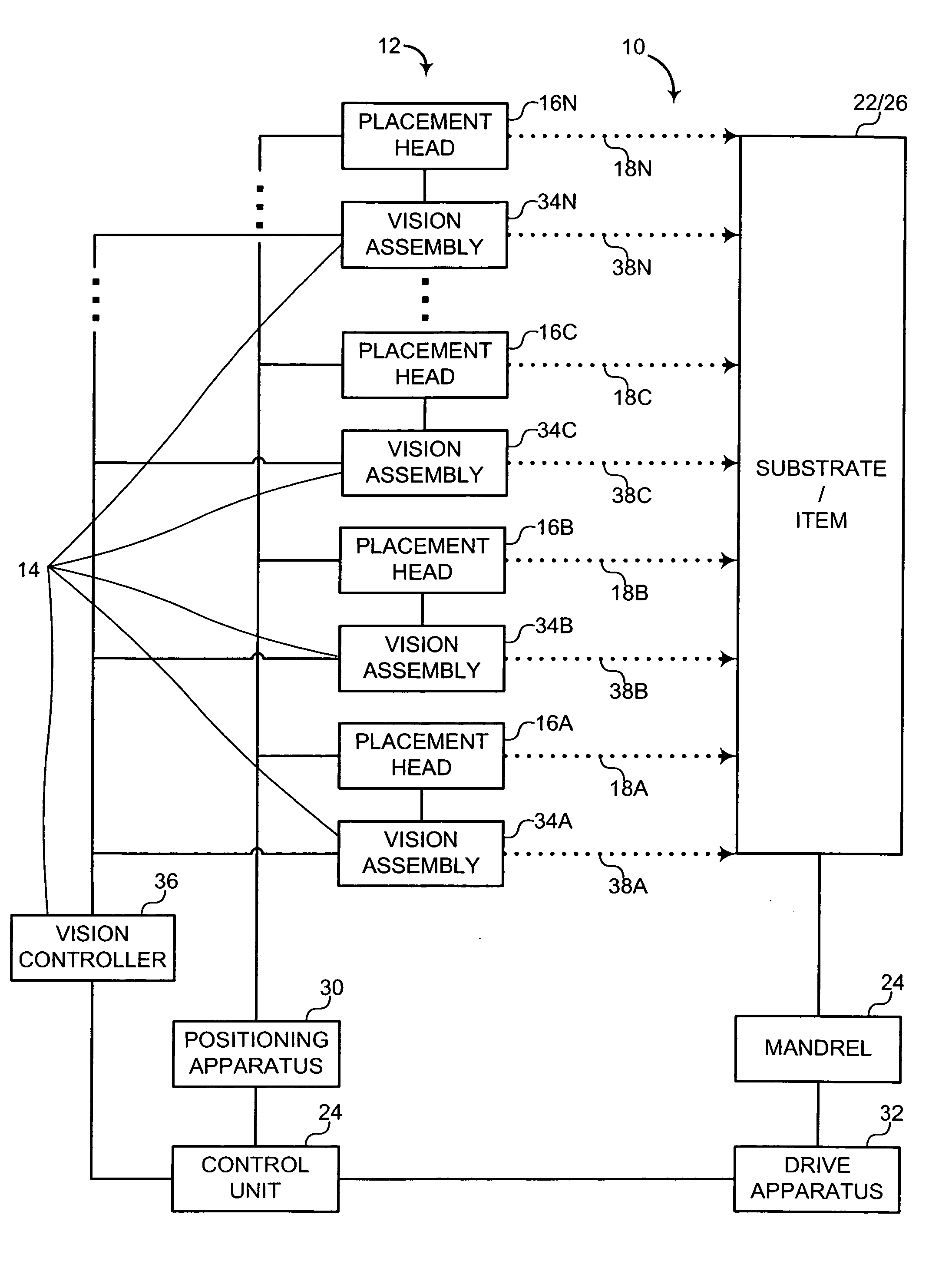
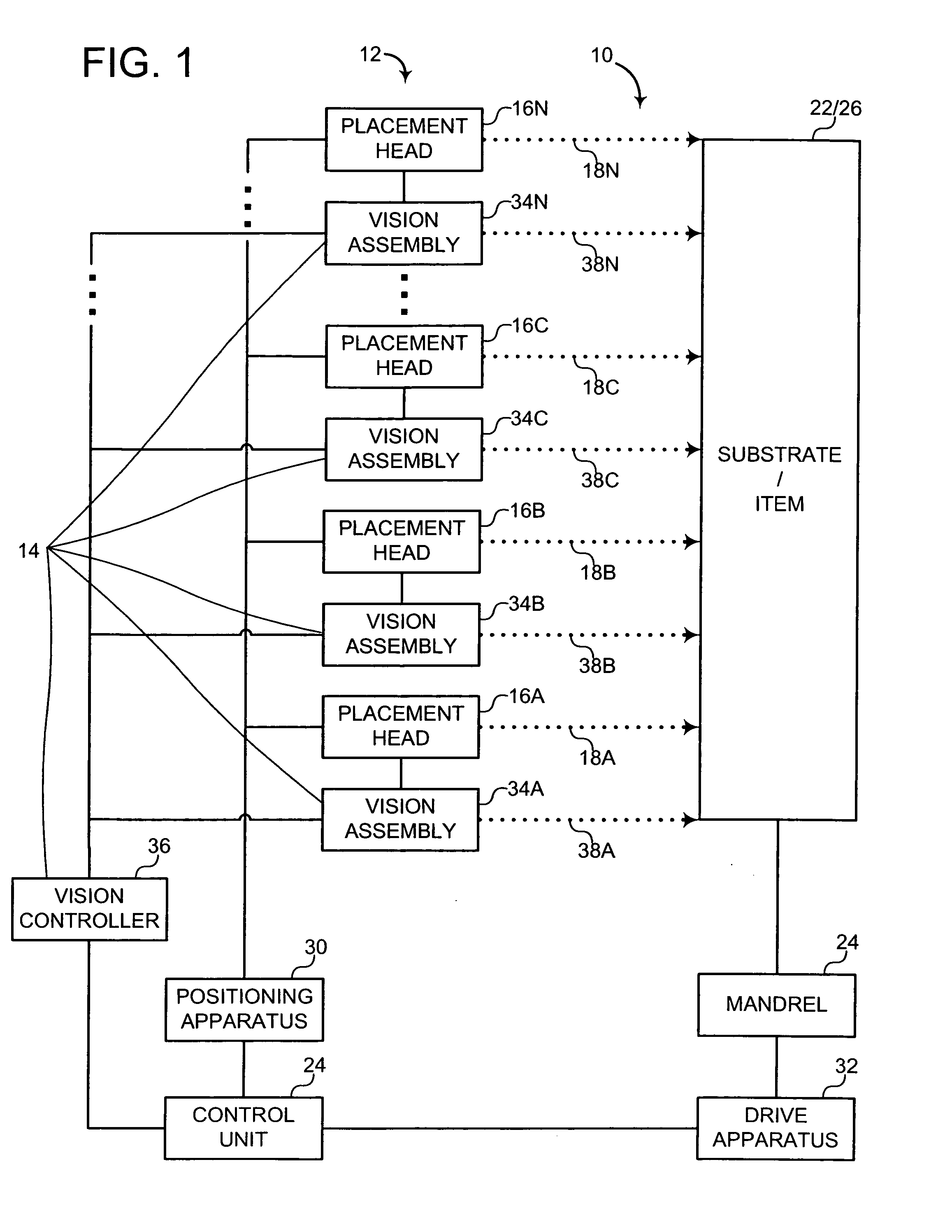
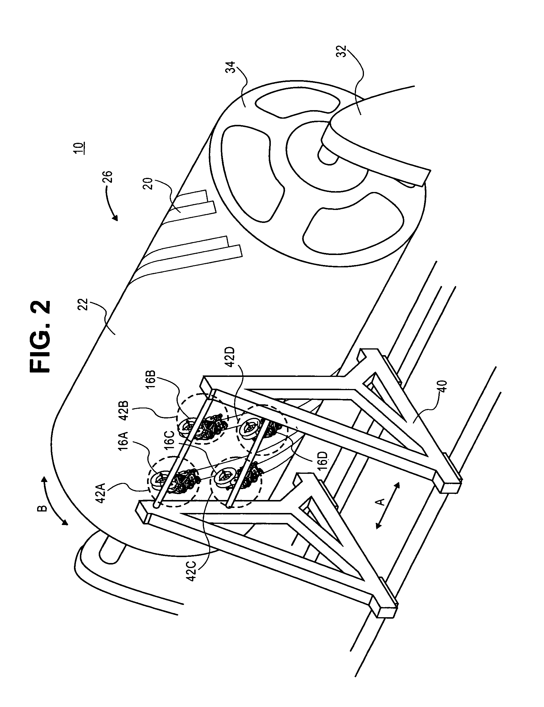
[0019] The present invention provides, in some embodiments, an in-process, machine vision, inspection system for a composite placement device and a method of using this system. In various embodiments, the system is suitable for use with an automated lamination device such as, for example, an automated fiber placement (AFP) machine, flat tape lamination machine (FTLM), numerically controlled (NC) contoured tape lamination machine (CTLM), multi-head tape lamination machine (MHTLM), and the like. These automated lamination devices generally include at least one placement head or “head” to place plies of composite material upon a mandrel, layup mold or tool to fabricate a composite item. The MHTLM may include a plurality of such heads. In an embodiment, the system includes a machine vision inspection assembly associated with each dispensing head of the MHTLM.

[0020] The invention will now be described with reference to the drawing figures, in which like reference numerals refer to like ...


PUM

PropertyMeasurementUnit
Angleaaaaaaaaaa
Areaaaaaaaaaaa

Abstract

A course material that is applied to a substrate during fabrication of a composite item is inspected by a system that includes a vision assembly. The vision assembly includes an area light, a line generator, a sensor, and an image processor. The area light illuminates an area of the course material. The line generator generates a line of illumination across the area. The sensor captures an image of the area. The image processor analyzes the image. The image processor is configured to identify debris on the course material in response to the area light being activated and the image processor is configured to identify placement aberrations in response to the line generator being activated.

Description

FIELD OF THE INVENTION [0001] The present invention generally relates to a machine vision inspection device. More particularly, the present invention pertains to a machine vision inspection device for use with a composite material placement system. BACKGROUND OF THE INVENTION [0002] Composite items are generally constructed from layers of material that are laminated together. These layers are often referred to as partial or full plies. For structures exceeding the available material width, each layer is typically made up of a series of strips or courses of material placed edge to edge next to each other or are overlapped to some extent. Each ply may be in the form of woven fibers in a fabric, unidirectional fiber material, metal foils, adhesive films or a variety of other conformations. Unidirectional fiber material is often termed, “tape.” The fibers may be made from any of a multitude of natural and / or “man-made” materials such as fiberglass, graphite, Kevlar®, and the like. [0003...

Claims


Application Information

Patent Timeline
IPC IPC(8): G01N21/88
CPCB29C70/32B29C70/386B29C70/388G01N2021/8472G01N21/8901G01N21/94G01N21/8806
Inventor ENGELBART, ROGER W.HANNEBAUM, REEDORR, SAMPOLLOCK, TIM
Owner THE BOEING CO
Why Eureka
Try Eureka