
Method and apparatus for 3-dimensional vision and inspection of ball and like protrusions of electronic components

a technology of electronic components and 3-dimensional vision, applied in the direction of 3d image data details, instruments, etc., can solve the problems of cumbersome halconTM matching methods, inaccurate, and ineffective approaches

Active Publication Date: 2010-12-30
MIT SEMICON (TIAN JIN) CO LTD
View PDF63 Cites 19 Cited by
  • Summary
  • Abstract
  • Description
  • Claims
  • Application Information

AI Technical Summary

Benefits of technology

[0019]We have now able to detect the conjugate point of ball tips using our own methodology and yet be able to compute the distance of ...

Problems solved by technology

Unfortunately, this approach is not useful when determining the distance to a small feature having varying surface curvature (hence varying distance) such as a contact solder ball tip of a ball grid array semiconductor package.
Using Halcon™ matching methods would be cumbersome and inaccurate for the purpose of determining the distance to the centre point of each ball or ball-like protrusion's curved surface as ball surface is void of textural features and is therefore not suitable for Halcon™ matching methods.

Method used


Image

  • Method and apparatus for 3-dimensional vision and inspection of ball and like protrusions of electronic components
  • Method and apparatus for 3-dimensional vision and inspection of ball and like protrusions of electronic components
  • Method and apparatus for 3-dimensional vision and inspection of ball and like protrusions of electronic components

Examples


Embodiment Construction

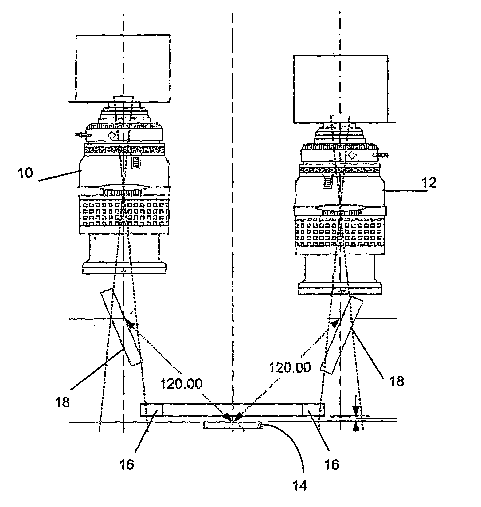
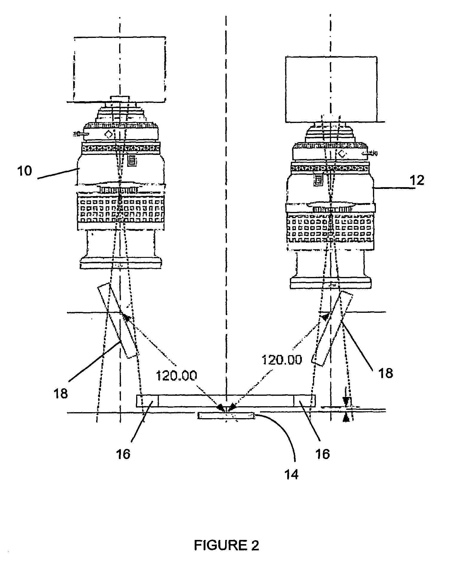
[0056]In the general embodiment of our invention's method may be implemented by a configuration or arrangement of a pair of cameras (10, 12) and other elements such as lighting elements including ring light (16) and reflective surfaces or mirrors (18) as shown in FIG. 2 in an elevation view.

[0057]Our novel method for 3-dimensional vision inspection covers objects (14) such as micro-electronic components having features to be inspected which may include input-output contact points protruding from the package, such as pins and balls of microelectronic packages, including pin grid array (PGA) packages, ball grid array (BGA) and like packages.

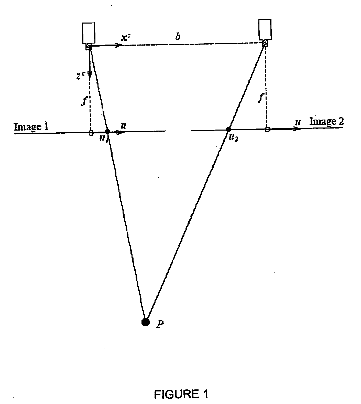
[0058]Our method includes the steps of:[0059](a) providing at least a pair of image capturing means with similar interior parameters arranged in a stereovision configuration;[0060](b) calibrating each of said image capturing means to determine the interior and exterior parameters of said image capturing means;[0061](c) forming a rectified coordinat...


PUM


Abstract

A method for 3-dimensional vision inspection of objects, such as microelectronic components, which have protrusions as features to be inspected, such as input / output contact balls, is disclosed. The method comprising the steps of determining interior and exterior parameters of a pair of cameras, forming a rectified coordinate system from the parameters of both cameras determined above with a relative pose of second image capturing means with respect to the first image capturing means. A pair of images of the object having a plurality of co-planar protrusions on one surface are captured by the cameras system wherein image coordinates of the images are transformed into coordinates of the rectified coordinate system. Conjugate points of each protrusion are then determined for the measurement of its co-planarity and height. Various configurations of the apparatus for capturing the images and processing the image data are also disclosed.

Description

TECHNICAL FIELD[0001]This invention relates to a method for inspecting objects in 3-dimensional vision, including inspecting electronic components which features' texture may require inspection that is detailed to a sub-pixel scale. An apparatus implementing such method is also disclosed.BACKGROUND OF THE INVENTION[0002]In a high-precision manufacturing environment where high volume of precision small objects are made, such as microelectronics fabrication and packaging of components, it is often necessary for each of the completed object such as a microelectronic package to be inspected for quality control purposes. Due to the large volume, such inspection has to be automated and due to the inspection involving examining specific critical feature of the package, such as co-planarity of the contact elements in the form of balls in a ball grid array (BGA) device, 3-dimensional vision is required.[0003]Some vision systems uses a single axial camera with a plurality of reflective surfac...

Claims


Application Information

Patent Timeline
IPC IPC(8): H04N13/02H04N13/239H04N13/243
CPCG01B11/0608G06T2207/30148G01N21/951G01N21/95684G06T7/0006G06T7/0075G06T2207/10012G06T2207/10152G06T2207/30152H04N13/0239H04N13/0242H04N13/0246H04N13/0253H05K13/08G06T7/004G06T2200/04G06T2207/30244G06T7/0004G06T7/0018G01N21/8806G06T7/80G06T7/70G06T7/593H04N13/239H05K13/0818H04N13/243H04N13/246H04N13/254
Inventor PUAH, YONG JOOTANG, HAK WEETEO, SOON POO
Owner MIT SEMICON (TIAN JIN) CO LTD
Learn More