In-circuit test fixture with integral vision inspection system

a technology of in-circuit test fixture and inspection system, which is applied in the direction of printed circuit testing, television system, instruments, etc., can solve the problems of missing common defects on pca assemblies, difficult in-circuit test, and many different types of defects in printed circuit assemblies

Inactive Publication Date: 2007-01-18
AGILENT TECH INC
View PDF8 Cites 18 Cited by
  • Summary
  • Abstract
  • Description
  • Claims
  • Application Information

AI Technical Summary

Problems solved by technology

A printed circuit assembly (“PCA”) is subject to many different types of defects during the assembly process.
However, as physical access to nodes on the PCA via bed-of-nails probing decreases, in-circuit test is becoming more difficult.
Some prevalent defects on PCA assemblies are missing, incorrect type or mis-oriented components.
Missing components can occur when the components are either never loaded onto the board or they fall off during the assembly process.
An incorrect type of component can occur when a component with the wrong electrical value is inadvertently loaded onto the board.
Improperly oriented components can occur when a component is loaded onto the board with a reversed polarity.
The above techniques each require at least some physical probing of the PCA nodes and are therefore ineffective for PCA assemblies ...

Method used


Image

  • In-circuit test fixture with integral vision inspection system
  • In-circuit test fixture with integral vision inspection system
  • In-circuit test fixture with integral vision inspection system

Examples


Embodiment Construction

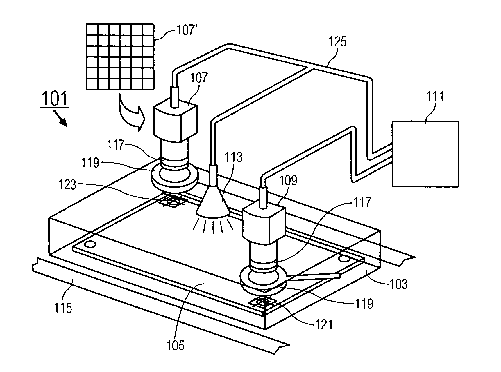
[0025]FIG. 1 shows one embodiment of the in-circuit test fixture with an integral vision inspection system 101 of the present invention. A test fixture 103 of an in-circuit tester 115 is shown positioned around a printed circuit assembly (“PCA”) 105. Only a small portion of the in-circuit tester 115 is shown in FIG. 1.

[0026] Mounted on the test fixture 103 are one or more digital cameras 107, 109. Each of the digital cameras has one or more light focusing means 117 which can be a lens or, in the case of pinhole cameras, can be a pinhole. The light focusing means 117 is used to image a feature of interest from the PCA 105. In this example, the features of interest are through-holes 121, 123. Examples of other features of interest are electrolytic capacitors, capacitors used as bypass capacitors, bead probes or, for example, any feature that is excluded from coverage during a previous ICT stage or which requires double-checking from a previous ICT stage. Each of the digital cameras 1...


PUM


Abstract

An in-circuit test fixture performs both electrical tests on a Printed Circuit Assembly (“PCA”) and reads distinguishing features of a feature of interest of the PCA. The in-circuit test fixture physically supports an image sensor array. A light focusing means has a position relative to the distinguishing features and the image sensor such that a focused real image of the distinguishing features is imaged onto the image sensor. The image sensor outputs image information of the distinguishing features. A processor performs image analysis based on the image information of the distinguishing features to determine if defects exist.

Description

FIELD OF THE INVENTION [0001] The invention relates to the field of the automated testing of printed circuit assembly assemblies. BACKGROUND OF THE INVENTION [0002] A printed circuit assembly (“PCA”) is subject to many different types of defects during the assembly process. Accordingly, various test and inspection techniques are employed to locate these defects. Today, there are three general test methods used to find PCA defects: electrical test, optical (or visual) inspection, and x-ray inspection. Of these, electrical test, and in particular a technique known as “in-circuit test”, is the most mature and most commonly used technique. However, as physical access to nodes on the PCA via bed-of-nails probing decreases, in-circuit test is becoming more difficult. [0003] Some prevalent defects on PCA assemblies are missing, incorrect type or mis-oriented components. Missing components can occur when the components are either never loaded onto the board or they fall off during the assem...

Claims


Application Information

Patent Timeline
IPC IPC(8): H04N7/18H04N9/47
CPCG01N21/95607G01N21/95684G01N2021/95638G01N2021/95646H05K13/08G01R31/2812G01R31/2813G01R31/309G01R31/31905G01R31/2808H01L21/82
Inventor THAM, YEW FEIYONG, WEE SHENGJACOBSEN, CHRIS RICHARD
Owner AGILENT TECH INC
Why Eureka
Try Eureka