Diffraction device

a diffraction device and diffraction grating technology, applied in the field of diffraction devices, can solve the problems of objectionably large pick-up assemblies, dip in diffraction efficiency at a certain wavelength, and degraded diffraction efficiency at other wavelengths, and achieve the effect of satisfying diffraction efficiency

Inactive Publication Date: 2007-10-04
FUJINON SANO
View PDF2 Cites 51 Cited by
  • Summary
  • Abstract
  • Description
  • Claims
  • Application Information

AI Technical Summary

Benefits of technology

[0012]By adoption of the construction as described above, it becomes possible to realize a diffraction device which can give a satisfactory diffraction efficiency free from dependency on wavelength and free from the direction of polarization of incident light.

Problems solved by technology

Use of three separate optical pickups independently for the respective disc formats results in a pickup assembly which is objectionably large in size, so that attempts have been made to provide a multi-disc optical pickup by incorporating component parts which are compatible with the three wavelengths.
Therefore, there has been a problem that a diffraction device which is attuned to one of CD, DVD and mass storage disc wavelengths can operate with a satisfactory diffraction efficiency at one wavelength but its diffraction efficiency is degraded at other wavelengths.
Of course, a dip in diffraction efficiency at a certain wavelength gives rise to problems such as reduction of light power of that wavelength and deterioration of power distribution ratio between a diffraction component of zero order and diffraction components of ±1 orders, making it difficult to keep stable supply of signal light and supply of focus error detection signal and tracking error detection signal as well.
That is to say, if the adjustments of various factors are imperfect, it becomes difficult to attain an aimed diffraction efficiency free of irregular variations.
On the contrary, strictness is pursued thoroughly in various adjustments, it makes the fabrication of the diffraction device difficult, giving rise to a serious problem such as a huge production cost.

Method used


Image

  • Diffraction device
  • Diffraction device
  • Diffraction device

Examples


Embodiment Construction

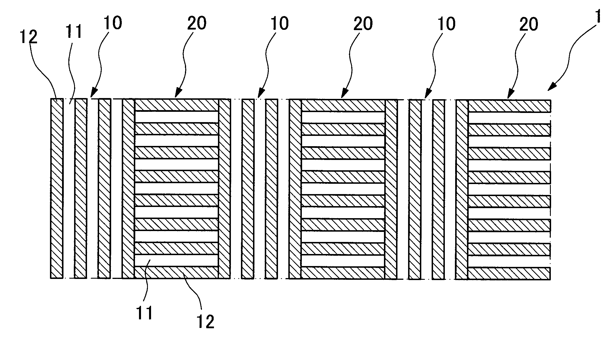
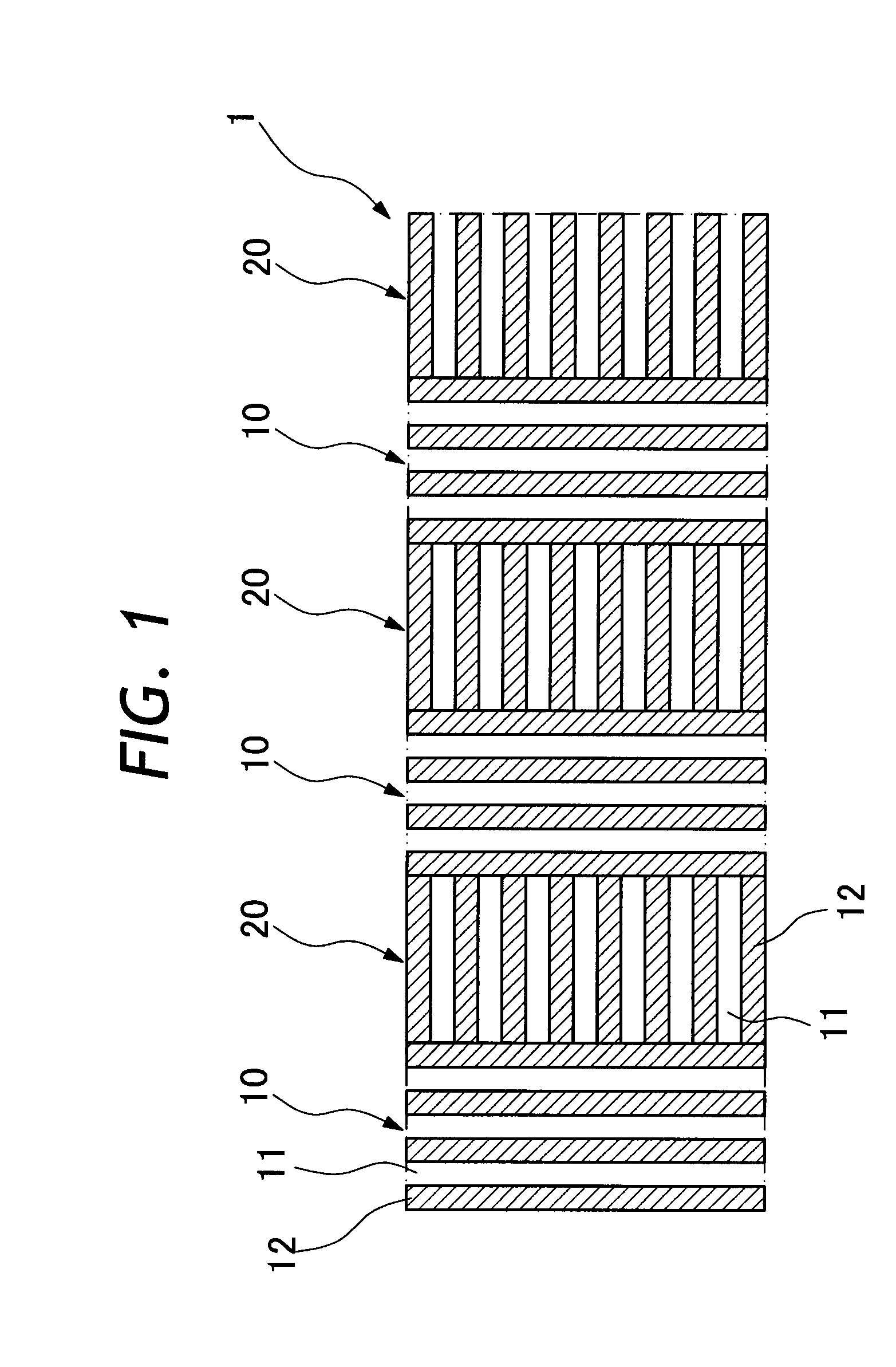
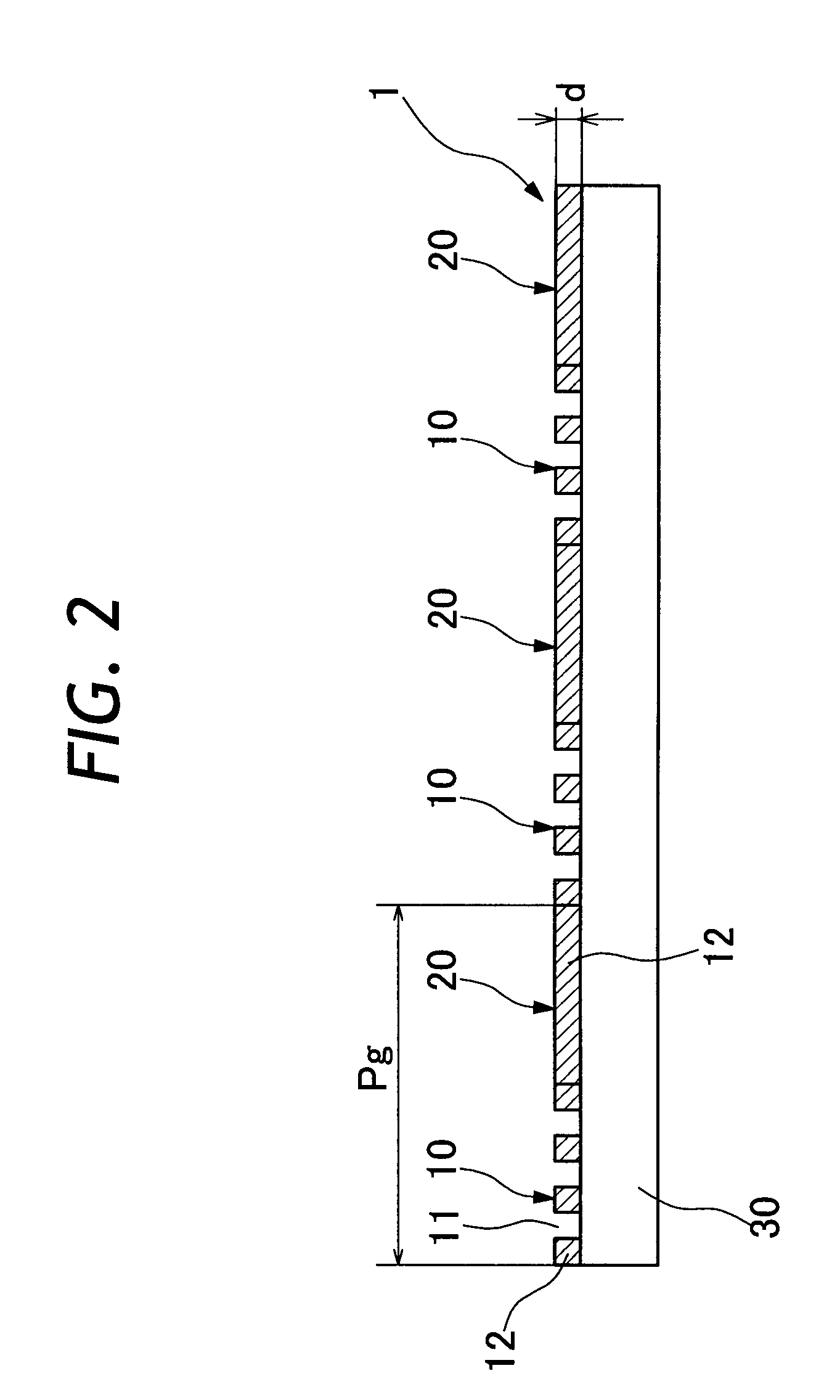
[0023]A. Construction of Diffraction Device

[0024]Now, the present invention is described more particularly by way of its preferred embodiments with reference to the accompanying drawings. Shown in FIGS. 1 and 2 is a diffraction device 1 according to the invention, the diffraction device 1 having an array of first phase control zones 10 and second phase control zones 20 formed on a transparent substrate plate 30 like a glass plate. As shown in FIG. 1, the diffraction device 1 is of a periodic structure having the first phase control zones 10 and the second phase control zones 20 periodically in alternate positions. As shown also in FIG. 3, each one of the first and second phase control zones 10 and 20 has a ruled surface structure of an infinitesimally small pitch. The ruled structure of an infinitesimal pitch is formed by transferring low and high surface profiles to a plastic or synthetic resin material or by engraving grooves on a surface of the transparent substrate plate 30 itse...


PUM


Abstract

A diffraction device having, on a transparent substrate plate, a diffraction pattern composed of periodically alternating array of first and second phase control zones. Each one of the first and second phase control zones is provided with an infinitesimal ruled structure in a pitch of the order of sub-wavelength, i.e., in a pitch smaller than the shortest wavelength of incident light, thereby to control phase shifts to the same angle in a plural number of wave ranges. The infinitesimal ruled structure in the first and second phase control zones are disposed in perpendicularly intersecting relation with each other. Thus, the diffraction device can diffract incident light with a diffraction efficiency free from dependency on wavelength and give a performance not dependent on the direction of polarization of incident light.

Description

BACKGROUND OF THE INVENTION[0001]1. Field of the Art[0002]This invention relates to a diffraction device useful for diffraction of incident light, and more particularly to a diffraction device which can give a performance barely dependent on wavelength.[0003]2. Prior Art[0004]Diffraction devices have been known and in use for diffraction of incident light. For example, diffraction device are used on optical pickups. In the case of an optical pickup, a light beam emitted from a light source is utilized not only as signal light but also as a focus error detection signal and a tracking error detection signal. Incident light is diffracted into a number of diffraction components including signal light of zero order and focus error detection signal light and tracking error detection signal light of ±1 orders. For this purpose, a diffraction device has a minutely ruled structure of the order of microns on a glass substrate plate.[0005]Lately coming into wide use are optical pickups which a...

Claims


Application Information

Patent Timeline
Patent Type & Authority Applications(United States)
IPC IPC(8): G02B5/18
CPCG02B5/1809
Inventor KAWAMURA, YOSHIJIKURAHASHI, HAJIME
Owner FUJINON SANO
Why Eureka
Try Eureka