Interference solar selective heat absorption coating layer

A technology of heat-absorbing coatings and solar energy, applied in solar thermal power generation, solar thermal devices, coatings, etc., can solve problems such as poor stability, attenuation of heat-absorbing performance, and easy oxidation

Inactive Publication Date: 2015-12-23
佛山圣哥拉太阳能科技有限公司
View PDF10 Cites 13 Cited by
  • Summary
  • Abstract
  • Description
  • Claims
  • Application Information

AI Technical Summary

Problems solved by technology

[0004] The purpose of the present invention is to solve the problems in the prior art that the interference-type selective heat-absorbing coating is easily oxidized, poor in stability, and attenuated in heat-absorbing performance when exposed to the air, and to provide an interference-type coating with better stability and weather resistance. Type Solar Selective Heat Absorbing Coating

Method used


Image

  • Interference solar selective heat absorption coating layer
  • Interference solar selective heat absorption coating layer
  • Interference solar selective heat absorption coating layer

Examples


Embodiment 1

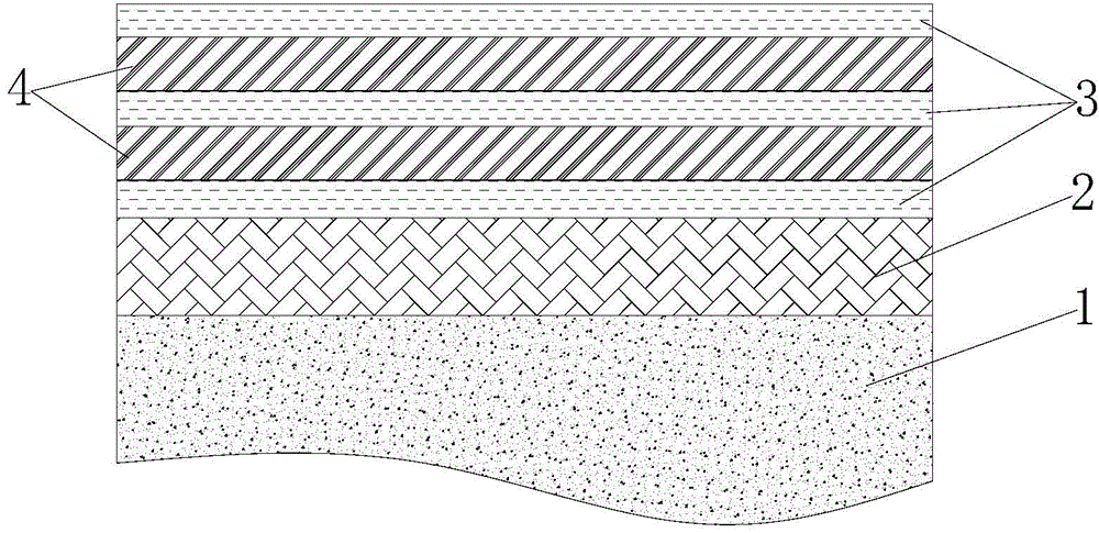
[0017] Choose aluminum as the substrate of the heat-absorbing coating, and prepare 5nm chromium, 40nm silicon nitride, 25nm chromium nitride, 10nm silicon nitride, 15nm chromium nitride and 60nm silicon nitride from the substrate upwards by magnetron sputtering . Among them, silicon nitride is prepared by reactive sputtering of silicon target in nitrogen environment, and chromium nitride is prepared by reactive sputtering of metal chromium target in nitrogen environment. Thus, a blue heat-absorbing coating with excellent performance is obtained. After testing, the coating has an absorptivity of 0.952 and a thermal emissivity of 0.04.

[0018] Such as figure 1 As shown, the aluminum layer is the substrate 1 , the chromium layer is the metal bonding layer 2 , the silicon nitride layer is the transparent medium layer 3 , and the chromium nitride layer is the compound material absorption layer 4 .

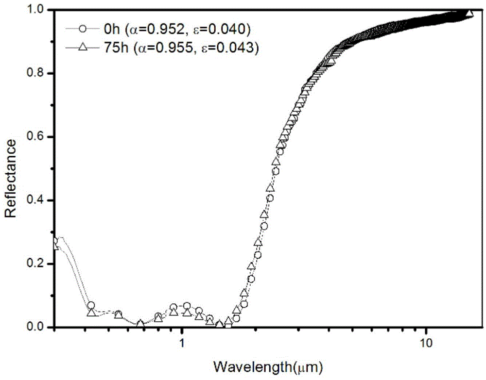
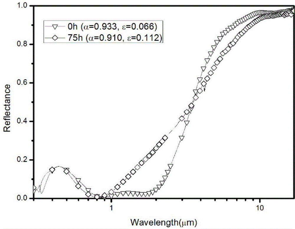
[0019] Such as figure 2 and image 3 As shown, the absorptivity and emissivit...

Embodiment 2

[0021] The aluminum after anodic oxidation and surface treatment is selected as the substrate of the heat-absorbing coating, and a 5nm titanium layer, 40nm silicon nitride, 35nm titanium carbide, 23nm silicon nitride, and 23nm carbon carbide are prepared from the substrate upwards by magnetron sputtering. Titanium and 65nm silicon nitride. Among them, silicon nitride is prepared by reactive sputtering of silicon target in nitrogen environment, and titanium nitride is prepared by reactive sputtering of metal titanium target in nitrogen environment. The obtained heat-absorbing coating is blue, and after testing, the absorptivity is 0.946, and the thermal emissivity is 0.045.

Embodiment 3

[0023] Choose copper as the substrate of the heat-absorbing coating, and prepare 4nm titanium, 26nm titanium nitride, 30nm aluminum nitride, 20nm titanium nitride, 30nm aluminum nitride, 15nm titanium nitride, 24nm aluminum nitride, and 10nm nitrogen from the substrate upwards. TiO, 55nm Aluminum Nitride. Among them, aluminum nitride is prepared by reactive sputtering of aluminum target in nitrogen environment, and titanium nitride is prepared by reactive sputtering of metal titanium target in nitrogen environment. The layer was tested to have an absorptivity of 0.942% and a thermal emissivity of 0.038.


PUM


Abstract

The invention provides an interference solar selective heat absorption coating layer. A substrate is coated with the coating layer, and the coating layer comprises a composite absorption layer formed through periodic alternative deposition of transparent dielectric layers and compound material absorption layers; and the material of the compound material absorption layers is selected from one of chromium nitrides, chromium carbides, titanium nitrides, titanium carbides, titanium and chromium alloy nitrides, and titanium and chromium alloy carbides. Compared with traditional pure metal absorption layers, the compound material absorption layer has better physical and chemical stability, has very strong delustring capability in the solar spectrum area, and can substantially improve the weatherability of the coating layer.

Description

technical field [0001] The invention belongs to the technical field of solar thermal utilization, in particular to an interference type solar selective heat absorbing coating used on flat solar heat collectors. Background technique [0002] In the field of flat solar collectors, the metal-ceramic selective absorption coating is currently the most widely used, which mainly relies on metal nanoparticles in the film to absorb sunlight, such as the well-known Al 2 o 3 : W or Mo heat-absorbing coating, peroxide or oxynitride such as CrO x :Cr or NiCrO y N x : NiCr and other heat-absorbing coatings. However, although this type of coating is easy to prepare, if it is exposed to the atmosphere for a long time, especially in the air with strong acidity and alkalinity, the weather resistance of the coating is not ideal, and the optical performance and heat absorption effect will be greatly attenuated and eventually Failure, which is mainly due to the oxidation of metal nanopartic...

Claims


Application Information

Patent Timeline
Patent Type & Authority Applications(China)
IPC IPC(8): C23C14/06C23C14/34B32B9/00F24J2/48
CPCF24S70/30F24S70/225Y02E10/40
Inventor 徐刚熊斌孙耀明黄华凛史继富
Owner 佛山圣哥拉太阳能科技有限公司
Why Eureka
Try Eureka