Electrical circuit for a self-retaining relay
a self-retaining relay and circuit technology, applied in relays, electromagnetic relays, electric devices, etc., can solve the problems of complex and therefore expensive, rather space-consuming, and the operation of the known self-retaining relay circuit is rather narrow
- Summary
- Abstract
- Description
- Claims
- Application Information
AI Technical Summary
Benefits of technology
Problems solved by technology
Method used
Image

Examples
Embodiment Construction
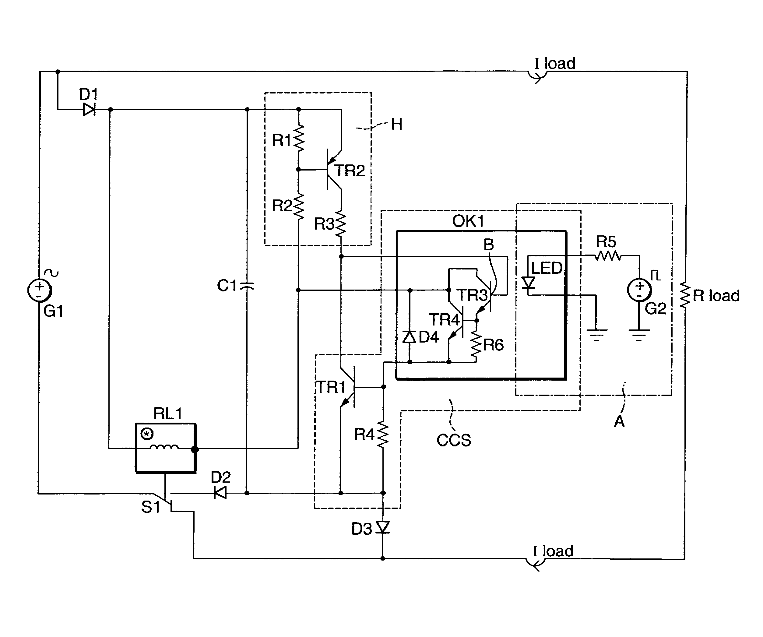
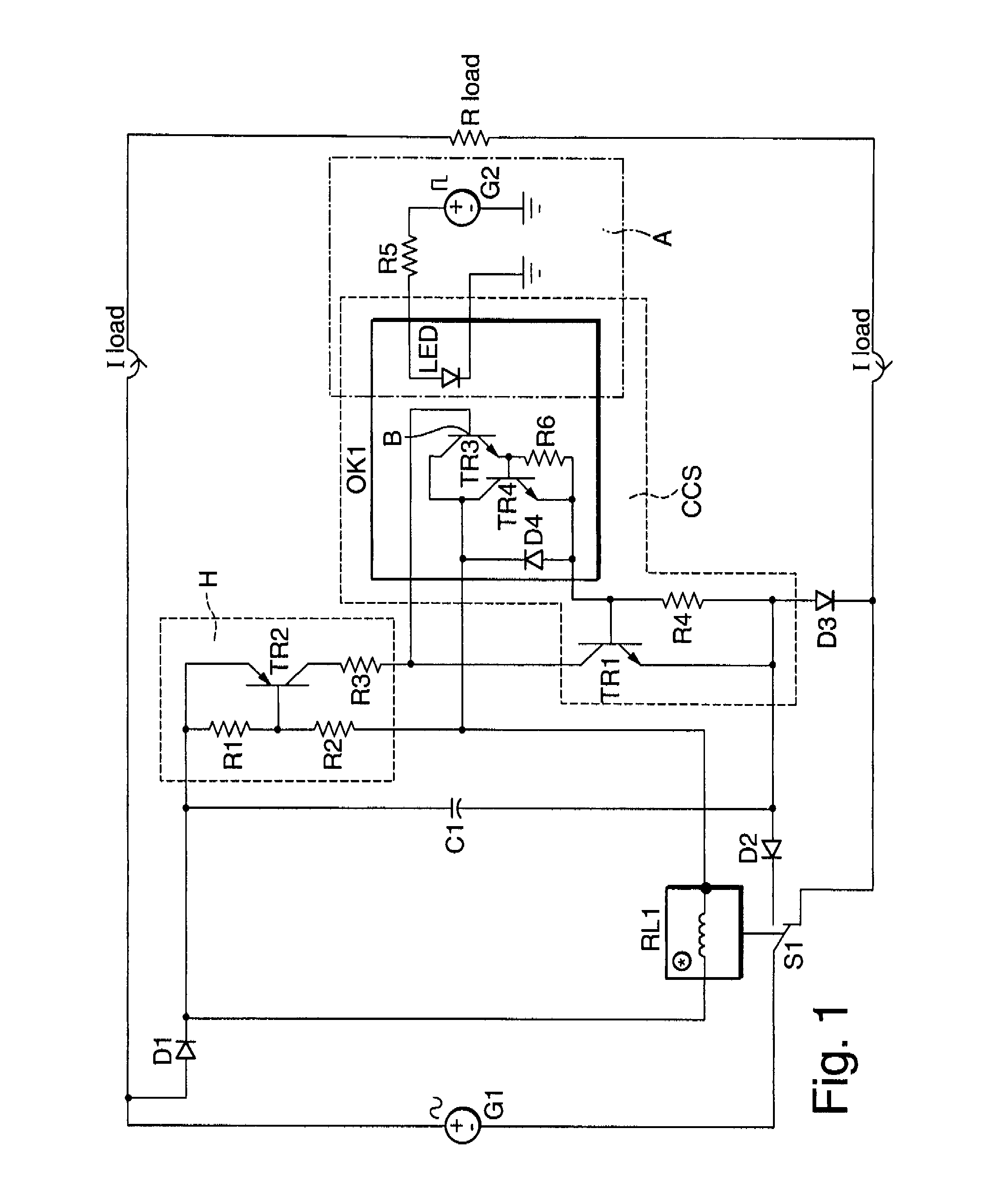
[0013]In a highly preferred embodiment of the inventive electrical relay circuit, the constant current source comprises an optical coupler connected to a resistor and the basis of a transistor. This is a simple way to realize the constant current source. With the optical coupler, the potentials of the relay and the first generator are insulated against the potential of the second generator. This increases the safety.
[0014]Another preferred embodiment is characterized in that the activation circuit comprises a light emitting diode (=LED), coupled to an optical coupler. The LED is a reliable tool to activate the optical coupler, which is part of the constant current source.
[0015]In a preferred further development of these embodiments, the optic coupler comprises a darlington circuit, with a photocell connected to the basis of the darlington circuit. Alternatively, a darlington circuit can be used wherein the basis can be illuminated directly. The darlington circuit amplifies a photo c...
PUM
 Abstract
Description
Claims
Application Information