Monitoring technique of a device connected to a network

a network monitoring and device technology, applied in the field of device monitoring techniques, can solve the problems of printer monitoring apparatus not being able to send snmp messages to the printer, ip address may change, etc., and achieve the effect of improving the reliability of management information acquisition

Active Publication Date: 2007-10-04
SEIKO EPSON CORP
View PDF7 Cites 34 Cited by
  • Summary
  • Abstract
  • Description
  • Claims
  • Application Information

AI Technical Summary

Benefits of technology

[0008]An object of the present invention is to provide a technology that improves the reliability of acquisition of management information from a network device.
[0010]With this arrangement, a network identifier contained in a message sent on the network by the network device is extracted. With the extracted network identifier, the monitoring apparatus may identify the device subject to monitoring. This allows the monitoring apparatus to acquire management information from the device subject to monitoring much reliably.

Problems solved by technology

However, with SNMP, the destination of the sending and receiving message is identified by an IP address, so a problem may arise under environments in which the IP address may change.
In these cases, there is the risk that the printer monitoring apparatus is not able to send SNMP messages to the printer subject to monitoring, and to acquire the management information.
This problem is common not only to cases when the printer is identified by an IP address, but also generally in cases when the information for identifying the printer may change.
This problem is also common not only to a printer monitoring apparatus that acquires printer management information, but also to other device monitoring apparatus that acquires management information of individual device connected to a network.

Method used


Image

  • Monitoring technique of a device connected to a network
  • Monitoring technique of a device connected to a network
  • Monitoring technique of a device connected to a network

Examples


first embodiment

A. First Embodiment

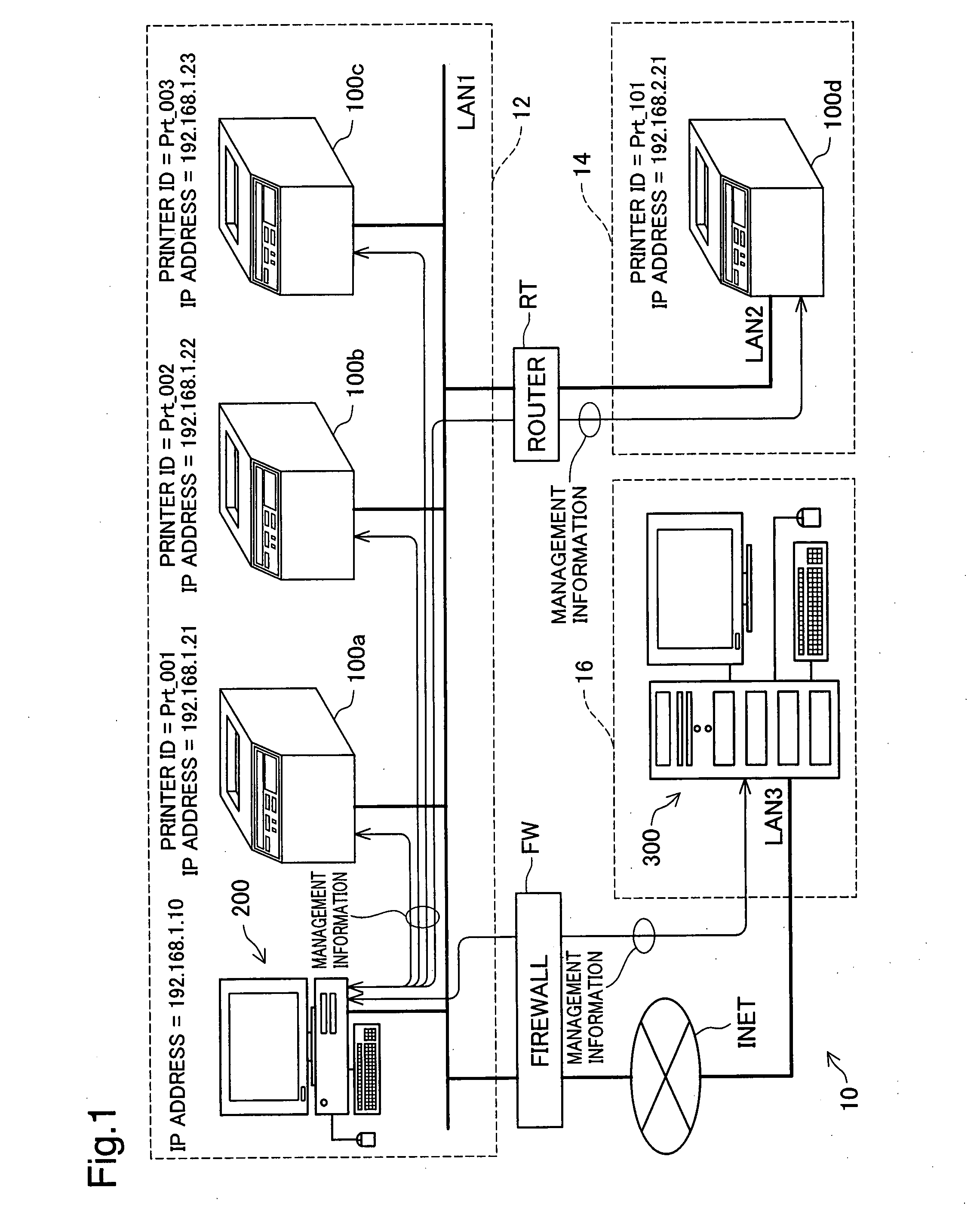
[0038]FIG. 1 is an explanatory drawing showing the configuration of the printer management system 10 in the first embodiment. In this printer management system 10, a first network system 12 and a second network system 14 are connected to each other via a router RT. The first network system 12 and a third network system 16 are connected to each other via a firewall FW and the internet INET.

[0039]These three network systems 12, 14, and 16 have network devices (hereafter also called simply “devices”) such as computers 200 and 300, and printers 100a to 100d. Data is sent and received between the devices according to TCP / IP protocol. In the first embodiment, a wired network specified by IEEE 802.3 is used for the local area networks LAN1, LAN2, and LAN3 that connect the devices in each of the network systems 12, 14, and 16. A wireless network system such as IEEE 802.11b / g / a may also be used for the local area networks LAN1, LAN2, and LAN3.

[0040]For each device of the f...

second embodiment

B. Second Embodiment

[0118]FIG. 9 is a flowchart showing the printer address monitoring routine executed by the address monitoring unit 226 (FIG. 2) with the second embodiment. The printer address monitoring routine of the second embodiment shown in FIG. 8 differs from the printer address monitoring routine of the first embodiment shown in FIG. 7 in that steps S270 and S280 are added, and in that when it is determined at step S240 that the specific device is not a monitoring subject printer, the control moves to step S270. The remaining points are the same as with the first embodiment.

[0119]At step S270, the address monitoring unit 226 determines whether or not the specific device is subject to monitoring by the monitoring PC 200 (FIG. 2). Specifically, a dialog box, which allows the user of the monitoring PC 200 to input an instruction whether or not to add the specific device as a monitoring subject, is displayed on a display (not illustrated) of the monitoring PC 200. Then, accord...

third embodiment

C. Third Embodiment

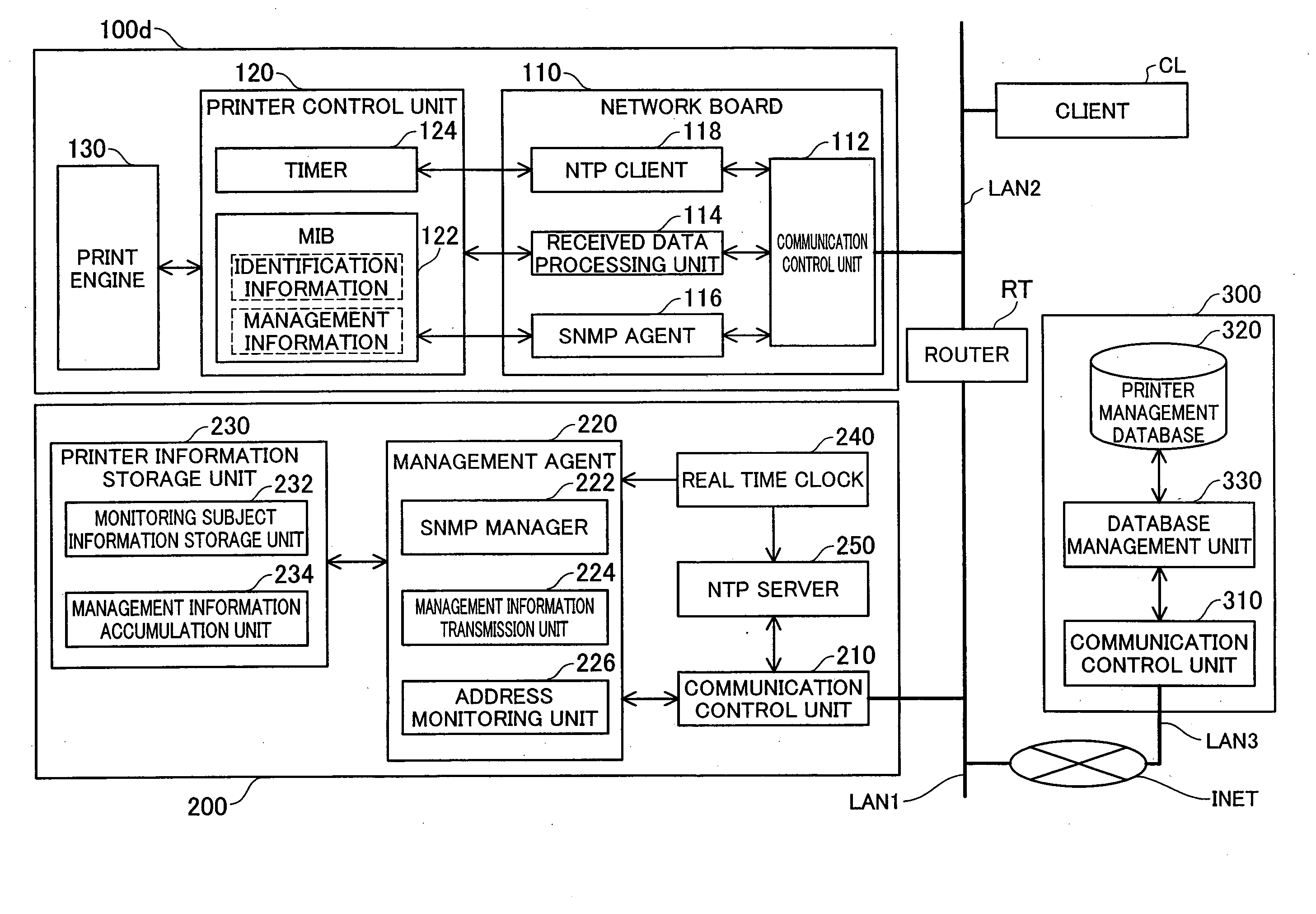
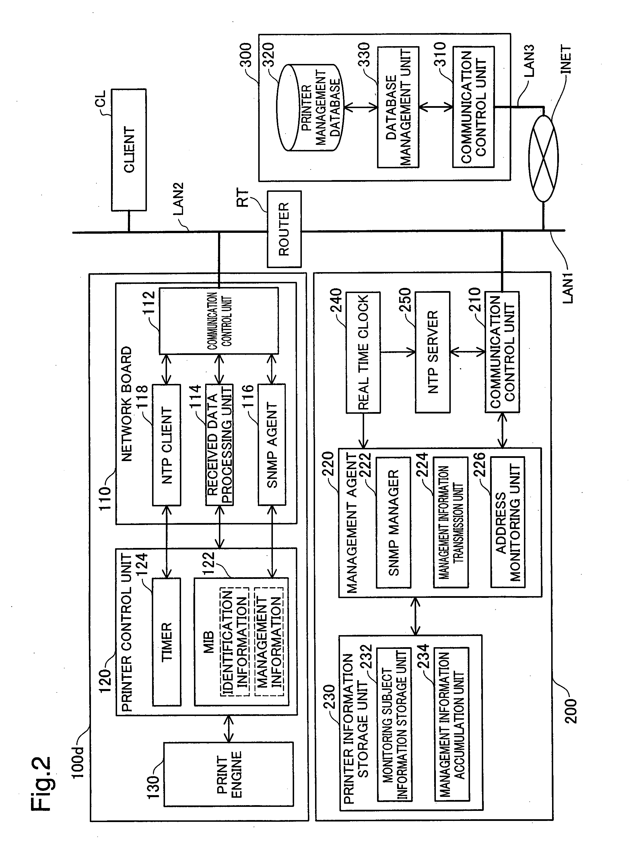
[0127]FIG. 11 is an explanatory drawing showing the configuration of the network device that constitutes the printer management system of the third embodiment. The printer management system of the third embodiment shown in FIG. 11 differs from the printer management system of the first embodiment shown in FIG. 2 in that the printer 100d and the monitoring PC 200 are replaced by the printer 10100d and the monitoring PC 10200 respectively, and in that a DNS (Domain Name System) server 500 is provided on the local area network LAN1. The remaining points are the same as with the first embodiment shown in FIG. 2.

[0128]The printer 10100d shown in FIG. 11 differs from the printer 100d shown in FIG. 2 in that it is equipped with a device registration unit 140 and in that the NTP client and the timer are omitted. The monitoring PC 10200 shown in FIG. 11 differs from the monitoring PC 200 shown in FIG. 2 in that the NTP server 250 is omitted.

[0129]The device registration un...


PUM


Abstract

The invention provides a technique improving the reliability of acquisition of management information from a network device. A monitoring apparatus has a network device identifier extraction unit configured to extract a network device identifier to identify a network device in the network from communication data sent over the network by the network device, the network device identifier assigned to the network device being changeable over time; an individual identification information acquiring unit configured to acquire an individual identification information from a specific network device that is identified by the network device identifier, the individual identification information uniquely and universally identifying the network device; a monitoring subject determination unit configured to determine whether the specific network device is a monitoring subject device that is subject to monitoring, based on the individual identification information; and a management information acquiring unit configured to acquire a management information from the specific network device when the specific network device is determined to be a monitoring subject device, the management information being an information relating to the specific network device and changing over time.

Description

CROSS-REFERENCE TO RELATED APPLICATIONS[0001]The present application claims the priority based on Japanese Patent Application No. 2006-101294 filed on Apr. 3, 2006 and Japanese Patent Application No. 2006-256165 filed on Sep. 21, 2006, the disclosures of which are hereby incorporated herein by reference in its entirety.BACKGROUND OF THE INVENTION[0002]1. Field of the Invention[0003]The present invention relates to a device monitoring technique that acquires management information from a device connected to a network.[0004]2. Description of the Related Art[0005]In a printer management system that manages a printer connected to a network, the management such as printer maintenance and accounting is performed based on specific management information. The management information may include information on the printer such as the total printed sheet count, trouble information, the print job count, and usage of consumable supply (for example, paper and toner) for each print job. To acquire...

Claims


Application Information

Patent Timeline
Patent Type & Authority Applications(United States)
IPC IPC(8): H04L12/56G06F13/00
CPCH04L41/0213H04L43/0817H04L41/046
Inventor SHIMA, TOSHIHIROABE, TAKUYAMATSUMOTO, AKIRA
Owner SEIKO EPSON CORP
Why Eureka
Try Eureka