Oil pump

An oil pump and oil cavity technology, applied in the field of automotive engineering, can solve the problems of low reliability of liquid level sensing and low accuracy of oil measurement, and achieve the improvement of the reliability of liquid level signal collection, the improvement of the ability to resist liquid level fluctuation, and the improvement of detection accuracy. boosted effect

Inactive Publication Date: 2017-07-07
WUHAN UNIV OF SCI & TECH
View PDF5 Cites 0 Cited by
  • Summary
  • Abstract
  • Description
  • Claims
  • Application Information

AI Technical Summary

Problems solved by technology

[0004] The invention provides an oil pump, which solves the technical problems of low reliability of liquid level sensing and low accuracy o

Method used


Image

  • Oil pump
  • Oil pump
  • Oil pump

Examples


Embodiment Construction

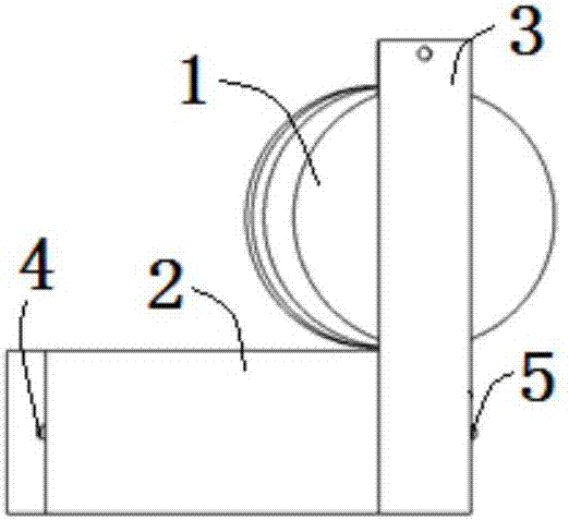
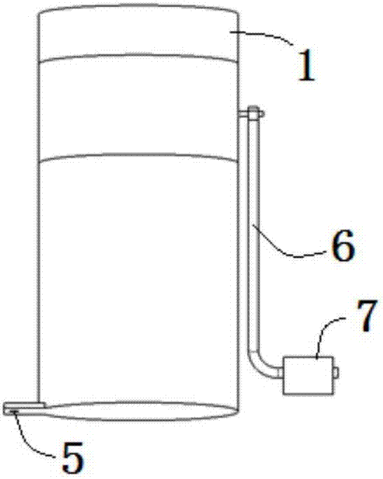
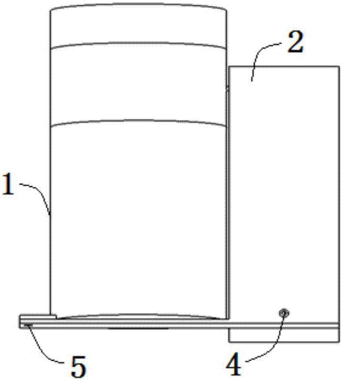
[0023] The embodiment of the present application provides an oil pump to solve the technical problems of low reliability of liquid level sensing and low accuracy of oil quantity measurement caused by the liquid level sensor in the automobile oil pump in the prior art; the anti-vibration ability is improved , the technical effect of oil quantity measurement accuracy.

[0024] In order to better understand the above technical solutions, the above technical solutions will be described in detail below in conjunction with the accompanying drawings and specific implementation methods. It should be understood that the embodiments of the present invention and the specific features in the embodiments are detailed descriptions of the technical solutions of the present application. , rather than limiting the technical solutions of the present application, the embodiments of the present application and the technical features in the embodiments can be combined without conflict.

[0025] se...


PUM


Abstract

The invention belongs to the technical field of automobile engineering and discloses an oil pump. The oil pump comprises an oil pump body, a liquid level sensor and a cavity. The bottom of the cavity communicates with an oil cavity of the oil pump body through an oil passing hole. The liquid level sensor is arranged in the cavity. The oil pump provided by the invention can accurately measure the oil amount and has good anti-oscillation capability.

Description

technical field [0001] The invention relates to the technical field of automobile engineering, in particular to an oil pump. Background technique [0002] At present, the remaining oil quantity of the car is mainly measured by the oil quantity sensor. The principle is that the oil float drives a wire-wound sliding resistor, and the oil level changes the resistance value of the sliding resistor, so that the oil quantity can be measured. [0003] The oil quantity sensor is widely used and has a simple structure. However, when the car is running bumpy or goes uphill or downhill for a long time, the oil level will fluctuate or be seriously inclined. Therefore, the collected resistance There will be a large deviation between the signal and the actual resistance value, and the oil volume data after the resistance conversion will have a large error, resulting in poor calculation accuracy of the cruising range and less guiding significance for the driver. Contents of the invention...

Claims


Application Information

Patent Timeline
IPC IPC(8): F04B51/00G01F23/24
CPCF04B51/00G01F23/245
Inventor 程峰郭健忠钱能谢斌吴建立
Owner WUHAN UNIV OF SCI & TECH
Why Eureka
Try Eureka