
Storage function method and apparatus in a passive optical network

a technology of passive optical network and storage function, which is applied in the field of storage function methods and equipment for implementing a storage function in a passive optical network system, can solve the problems of large downlink flow of this system, inability to solve the problem of bandwidth waste in the connection network (such as pon) portion of downlink bandwidth, and achieve the effect of improving the utilization factor

Inactive Publication Date: 2007-10-04
HITACHI LTD
View PDF23 Cites 11 Cited by
  • Summary
  • Abstract
  • Description
  • Claims
  • Application Information

AI Technical Summary

Benefits of technology

[0012]The present invention was submitted taking the aforementioned problems into consideration, the present invention having for an object to provide an implementation method of making a PON system store data, to avoid as far as possible duplicate transfers of data by ONUs within the PON system and, in particular, to avoid duplicate transfers of data making exclusive use of a comparatively wide bandwidth such as audiovisual data and big data packages, improve the utilization factor of the downlink bandwidth, and make it possible to reduce the congestion of information flow and data delays.
[0019]In the optical network unit of the passive optical network system of the present invention, there is provided a storage device, and since data making exclusive use of a comparatively wide bandwidth, such as audiovisual data, are stored in advance in this storage device, it is possible, in case the user on the optical network unit requests these data, to avoid as far as possible, without making exclusive use of the downlink portion from the core network to the optical network unit multiple times, duplicate transfers of data such as audiovisual data which make exclusive use of a comparatively wide bandwidth, to improve the utilization factor of the downlink bandwidth, and to reduce congestion of the flow and data delays.

Problems solved by technology

Since there is not any restriction with respect to the allocation of bandwidth for the downlink direction, the downlink bandwidth is shared by all ONUs, so for this reason, the downlink flow of this system becomes very big and there exist problems such as flow congestion and data delays.
However, the method presented in Patent Reference U.S. Pat. No. 5,550,577A can only solve the problem of bandwidth waste in the core network portion of the downlink bandwidth and is unable to solve the problem of bandwidth waste in the connection network (such as PON) portion of the downlink bandwidth.
Currently, the problems mentioned hereinafter exist in PON systems.
In case the user of a different ONU requires the same data, these data are sent from an IPTV server to reach the user via the entire PON system, and in this case, the result is that the same data makes exclusive use of the downlink bandwidth of the PON system multiple times, leading to a kind of serious waste of the bandwidth resource.
2. Due to the fact that audiovisual data for groupcast method transfers occupy a comparatively wide bandwidth and a different ONU user can only receive the data at the same time, he cannot view these data (e.g. viewing an audiovisual program) at a different time.
In other words, in case a markedly different ONU user wants to view the same program at a different time, there is a need to access the IPTV server multiple times, the result being that exclusive use is made of the downlink bandwidth multiple times, leading to serious waste of the bandwidth resource.

Method used


Image

  • Storage function method and apparatus in a passive optical network
  • Storage function method and apparatus in a passive optical network
  • Storage function method and apparatus in a passive optical network

Examples


first embodiment

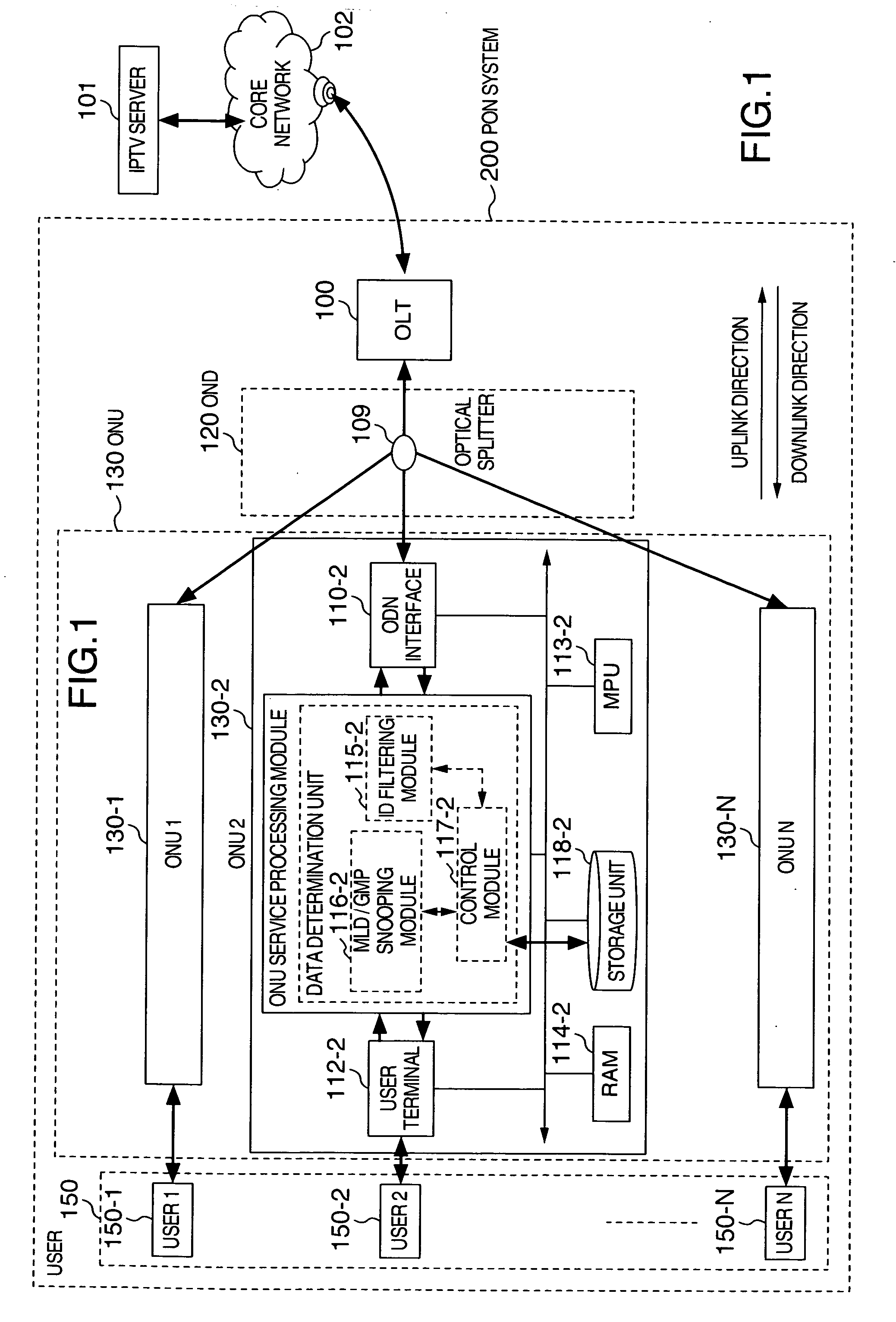
[0041]Hereinafter, an explanation will be given specifically of a passive optical network system of Embodiment 1 of the present invention, on the basis of FIGS. 1 to 4.

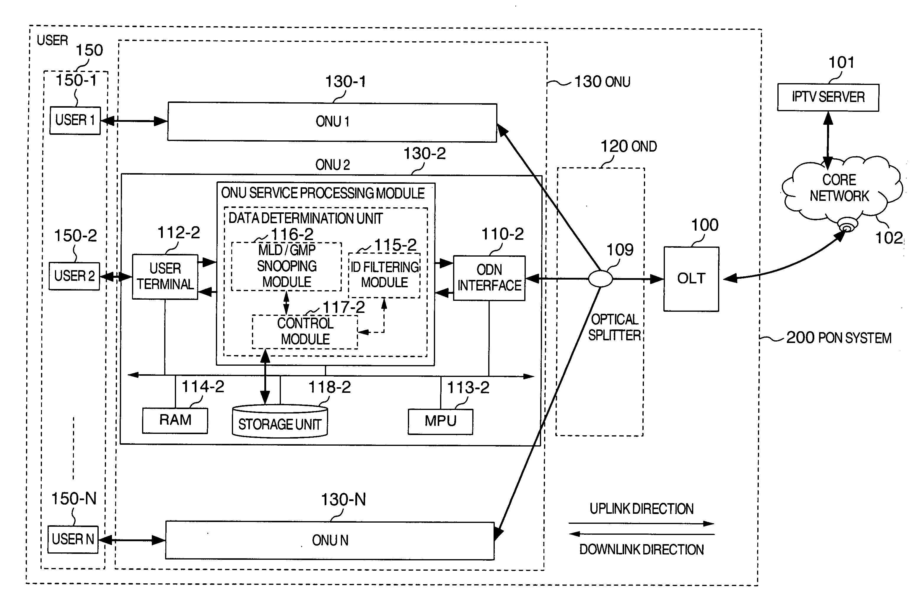
[0042]FIG. 1 is a structural frame diagram of a passive optical network system 200 having a storage function of Embodiment 1 of the present invention. In PON system 200, there are included an optical line terminal (below abbreviated as “OLT”) 100 connected to a core network 102 which is connected to an IPTV server 101, an optical distribution network (below abbreviated as “ODN”) 120 connected to OLT 100, and multiple optical network units (below abbreviated as “ONU”) 130-1, 130-2, . . . , 130-N (N expressing a positive integer greater than 1; below named generically as “ONU 130”) connected to ODN 120, and the like.

[0043]In ODN 120 therein, there is included an optical splitter 109. OLT 100 is located in a station terminal, and ONU 130, which is placed locally, shares an optical fiber located between OLT 100 and optica...

second embodiment

[0078]Based on FIG. 5 to FIG. 8, an explanation will hereinafter be given specifically regarding the data storage method of a passive optical network system of Embodiment 2 of the present invention.

[0079]FIG. 5 is a flowchart for storing, in the ONU storage device, data requiring storage in the downlink data, and for transferring data stored based on a user request.

[0080]First, by means of predetermined rules, data making exclusive use of a comparatively large bandwidth, such as e.g. audiovisual data and large data packages, are judged, from among all the data that have gradually been sent, to be data requiring storage (Step 501), on the basis of the LINK ID of the data. Thereafter, the previously determined data requiring storage are stored in storage device 118 of ONU 130 (Step 502). Supposing that it is the case that user 150 connected to ONU 130 had requested the data stored in storage device 118, the stored data are transferred directly to user 150 and if a request is made for ...

third embodiment

[0094]Based on FIG. 9 to FIG. 11, an explanation will hereinafter be given specifically regarding an OLT in a PON system of Embodiment 3 of the present invention.

[0095]FIG. 9 is a structural frame diagram of an OLT 100 having a groupcast LINK ID allocation module allocating groupcast LINK IDs with respect to the data. In OLT 100, there are mainly included an ODN interface 105, an OLT function processing module 104, a service terminal 103, a microprocessor unit (MPU) 106, a built-in read / write memory (RAM) 107, and the like. In the aforementioned OLT function processing module 104, there is included a groupcast LINK ID allocation module 108, and in this way, groupcast LINK IDs are allocated to data requiring storage (e.g. data making exclusive use of a comparatively wide bandwidth such as audiovisual data and large data packages). In case OLT function processing module 104 has detected data requiring storage coming from the IPTV server, one groupcast LINK ID is allocated to these dat...


PUM


Abstract

A method and an apparatus for implementing a storage function in a passive optical network (PON) system. On the basis of a LINK ID held by the data, data requiring storage, e.g. data making exclusive use of a wide bandwidth such as audiovisual data and large-volume data packages, are determined among all the data sent to an optical network unit. These data requiring storage are stored in a storage device installed in the optical network unit. In case the user requests data stored in the storage device, the stored data are transferred directly to the user, without any need to request and send these data for the second time via an IPTV server and the core network. It is possible to avoid duplicate transfers of data, and in particular to avoid duplicate transfers of data making exclusive use of a comparatively wide bandwidth such as audiovisual data and large-volume data packages, to improve the utilization factor of the downlink bandwidth, and to reduce flow congestion and data delays.

Description

CLAIM OF PRIORITY[0001]The present application claims priority from Chinese Application CN 200610071065.0, filed on Mar. 31, 2006, the contents of which are hereby incorporated by reference into this application.BACKGROUND OF THE INVENTION[0002]The present invention is one related to a method and equipment for implementing a storage function in a passive optical network system and which, in concrete terms, by utilizing a storage device installed in an optical network unit within the passive optical network system, stores data making exclusive use of a comparatively wide bandwidth such as e.g. audiovisual data, and transfers the data stored in the aforementioned storage device to the user.[0003]Since a Passive Optical Network (PON) has advantages like long distance capability, wide bandwidth, and low cost, it is already used as one of the most effective methods for end users connected to a network. A passive optical network system has an extended structure of the tree type or the lik...

Claims


Application Information

Patent Timeline
Patent Type & Authority Applications(United States)
IPC IPC(8): H04L12/56H04B10/27H04L12/44
CPCH04L29/08729H04N5/765H04N21/2541H04L65/4084H04N21/6405H04N21/64322H04N21/2747H04L67/568H04L65/612
Inventor IKEDA, HIROKIZHANG, NA
Owner HITACHI LTD
Learn More