Radial turbine wheel with locally curved trailing edge tip

a technology of local curved trailing edge tips and turbine wheels, which is applied in the field of radius turbine wheels, can solve the problems of high cycle fatigue of turbine wheel blades and inability to be easily manipulated

Inactive Publication Date: 2007-10-04
HONEYWELL INT INC
View PDF13 Cites 44 Cited by
  • Summary
  • Abstract
  • Description
  • Claims
  • Application Information

AI Technical Summary

Benefits of technology

[0006] In another aspect of the present invention there is provided a turbine wheel comprising: a hub; a central bore running longitudinally through the hub; long splitters and short splitter, the long and short splitters extending radially from the hub; a plurality of blades, the blades extending radially from the hub and being separated from one another by the long and short splitter, wherein the blade comprises a blade tip, the blade tip comprising a trailing edge; and wherein the trailing edge of the blade tip is curved.
[0007] In a further aspect of the presen

Problems solved by technology

High cycle fatigue of turbine wheel blades is a significant design problem because fatigue failure can result from resonant vibratory stresses sustained over a relatively short time.
Fatigue failure results from a combina

Method used


Image

  • Radial turbine wheel with locally curved trailing edge tip
  • Radial turbine wheel with locally curved trailing edge tip
  • Radial turbine wheel with locally curved trailing edge tip

Examples


Embodiment Construction

[0016] The following detailed description is of the best currently contemplated modes of carrying out the invention. The description is not to be taken in a limiting sense, but is made merely for the purpose of illustrating the general principles of the invention, since the scope of the invention is best defined by the appended claims.

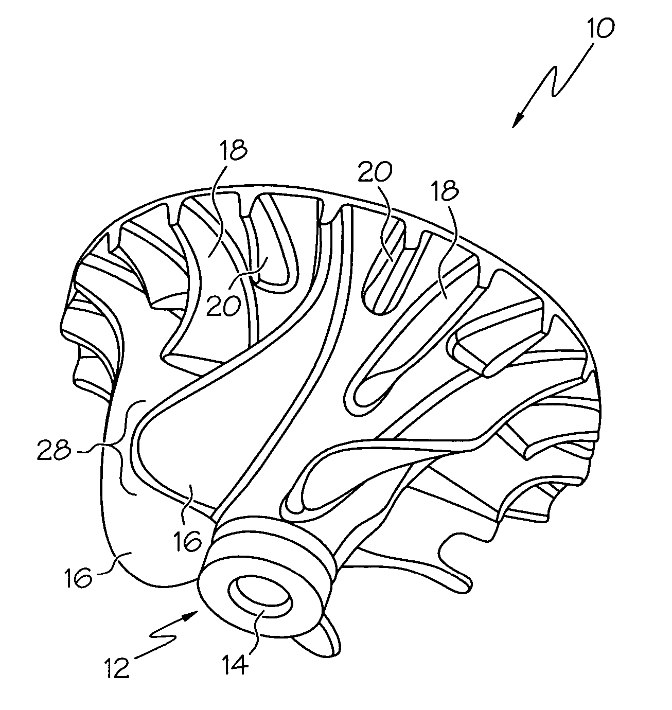
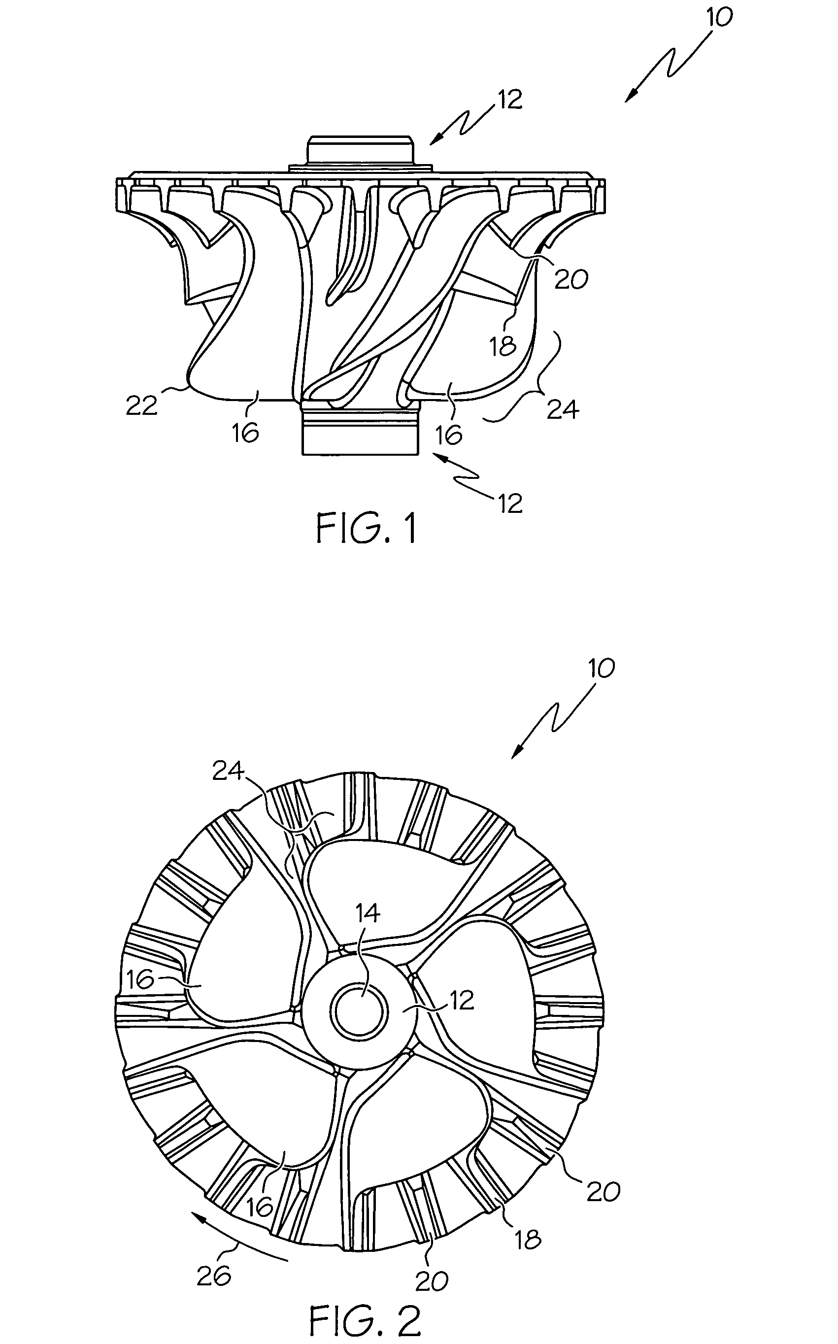
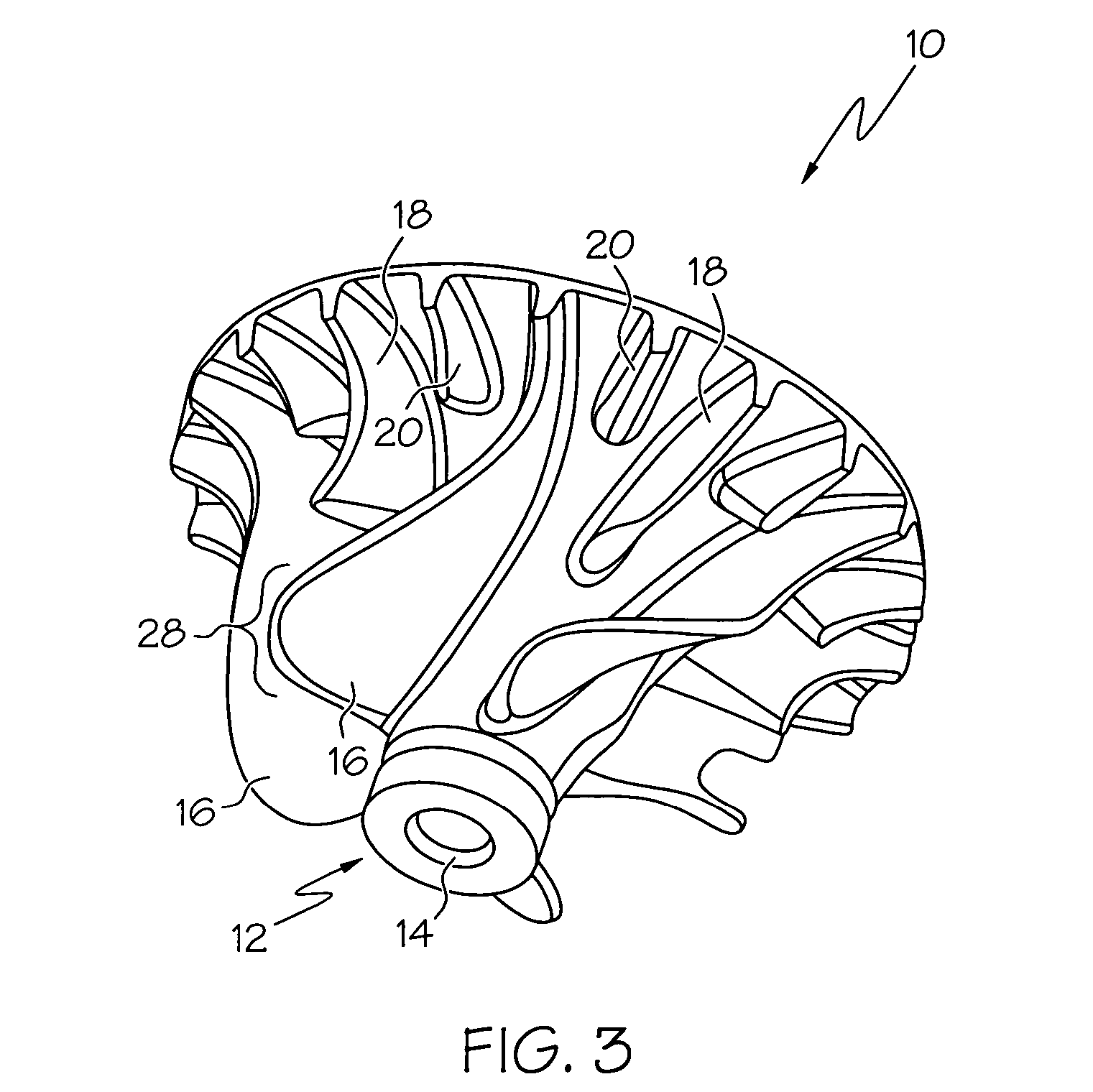
[0017] Broadly, the present invention provides a turbine wheel comprising blades having a locally curved trailing edge tip. The present invention also provides methods of using the turbine wheel of the present invention to control blade natural frequencies which may result in increased fatigue life of the blades and may also eliminate vortex shedding. The turbine wheel of the present invention may be used in gas turbine engines for applications in, but not limited to, aerospace.

[0018] The present invention provides a turbine wheel which may have increased blade fatigue life and no or reduced vortex shedding. This may be accomplished by having a local...


PUM


Abstract

The present invention provides a turbine wheel with locally curved trailing edge blade tips on the blades of the turbine wheel. The locally curved trailing edge may increase the blade vibration mode natural frequency which may in turn result in longer blade fatigue lifetimes. It may also eliminate vortex shedding. Methods for increasing the blade vibration mode natural frequencies using the turbine wheel of the present invention are also provided.

Description

BACKGROUND OF THE INVENTION [0001] This invention relates generally to radial turbine wheels and more specifically to radial turbine wheels having blades with locally curved trailing edge tips. [0002] High cycle fatigue of turbine wheel blades is a significant design problem because fatigue failure can result from resonant vibratory stresses sustained over a relatively short time. Fatigue failure results from a combination of steady stress and vibratory stress. The root cause of vibratory stress is flow-induced vibration at blade resonant frequency interfering with nozzle / vane passage frequency expressed in N per revolution with N=1, 2 . . . etc. For avoidance of high cycle fatigue failure due to vibratory stress, it would be preferable if the wheel has all blade vibration frequencies high enough that clears the vane count in the operating speed region. [0003] The prior art has attempted to reduce stresses on the turbine wheel blades by configuring blade geometry. In one turbine bla...

Claims


Application Information

Patent Timeline
IPC IPC(8): F03B7/00
CPCF01D5/048F01D5/16F05D2240/122F05D2250/71F05D2220/40F05D2260/96F05D2240/304
Inventor CHAING, WEI-SHINGLIN, FRANK F.OYOUNG, SHIOPING P.CHEN, ROBERT P.
Owner HONEYWELL INT INC
Why Eureka
Try Eureka