Active flow control for wind turbine blades

a technology of active flow control and wind turbine blades, which is applied in the direction of wind motor control, wind motors, motors, etc., can solve the problems of limiting the amount of power output that can be generated, and the slender blades are also subject to a limit in possible rated power, so as to increase the angle of attack range

Inactive Publication Date: 2007-10-04
GENERAL ELECTRIC CO
View PDF19 Cites 47 Cited by
  • Summary
  • Abstract
  • Description
  • Claims
  • Application Information

AI Technical Summary

Benefits of technology

[0006] One aspect of the present invention therefore provides a method for operating a wind turbine with at least one blade. The method includes providing at least one blade with at least one active flow control actua...

Problems solved by technology

These larger regions of separated flow limit the amount of power output that can be generated in a wind turbine belo...

Method used


Image

  • Active flow control for wind turbine blades
  • Active flow control for wind turbine blades
  • Active flow control for wind turbine blades

Examples


Embodiment Construction

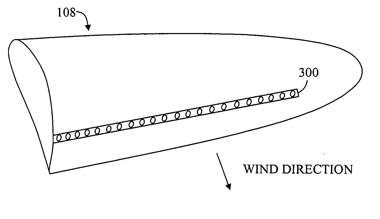
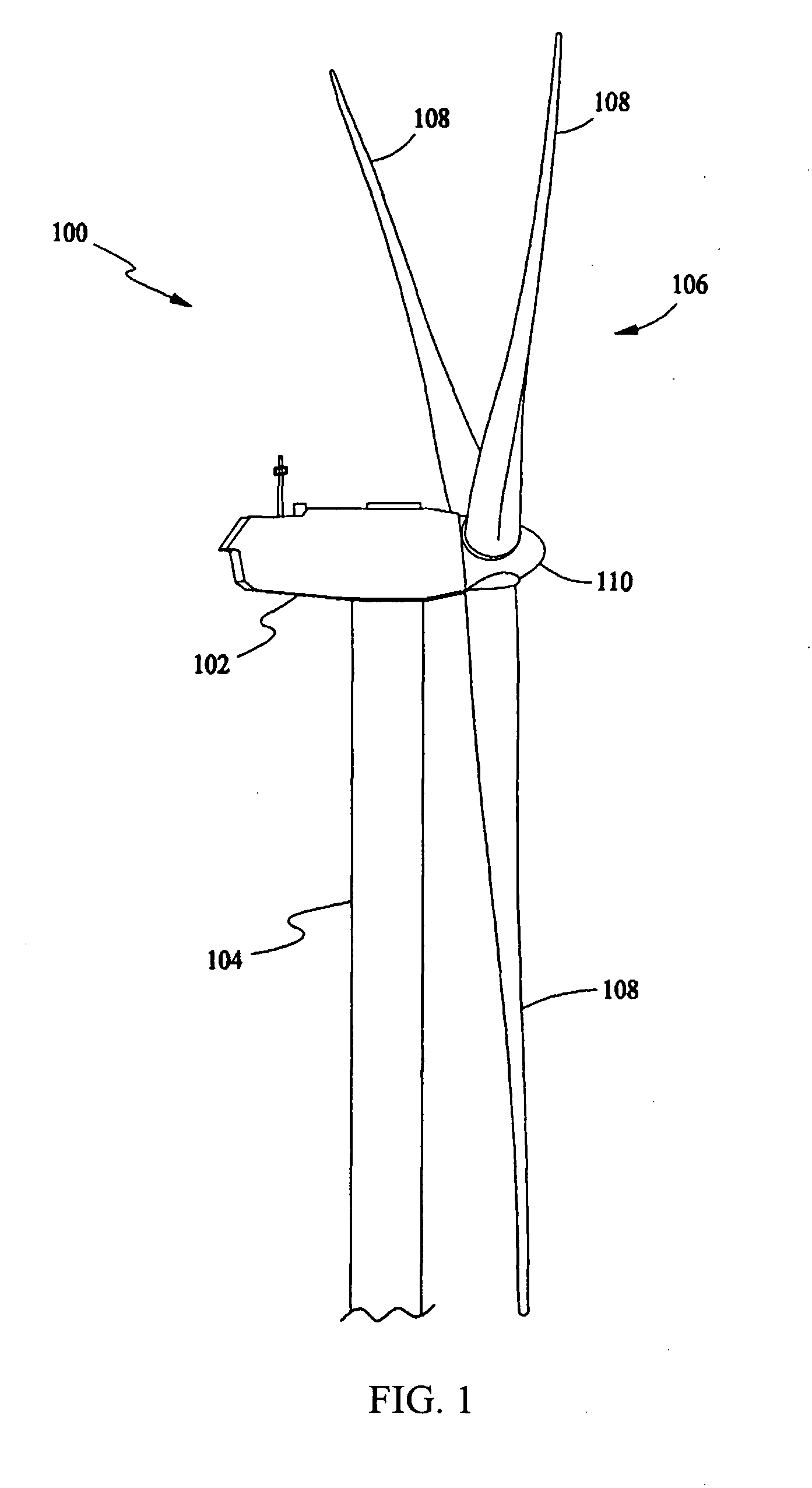
[0014] In some configurations and referring to FIG. 1, a wind turbine 100 comprises a nacelle 102 housing a generator (not shown in FIG. 1). Nacelle 102 is mounted atop a tall tower 104, only a portion of which is shown in FIG. 1. Wind turbine 100 also comprises a rotor 106 that includes one or more rotor blades 108 attached to a rotating hub 110. Although wind turbine 100 illustrated in FIG. 1 includes three rotor blades 108, there are no specific limits on the number of rotor blades 108 required by the present invention.

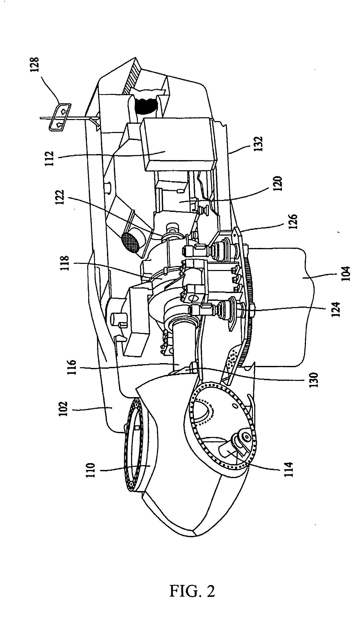
[0015] In some configurations and referring to FIG. 2, various components are housed in nacelle 102 atop tower 104 of wind turbine 100. The height of tower 104 is selected based upon factors and conditions known in the art. In some configurations, one or more microcontrollers within control panel 112 comprise a control system used for overall system monitoring and control. Alternative distributed or centralized control architectures are used in some configurations...


PUM


Abstract

A method for operating a wind turbine with at least one blade includes providing at least one blade with an active flow control actuator configured to increase an angle of attack range in which the blade or blades can generate torque without flow separation, and using the flow control actuator to adjust this angle of attack range in accordance with load.

Description

BACKGROUND OF THE INVENTION [0001] This invention relates generally to wind turbines, and more particularly to methods and apparatus for enhancing power output from wind turbines. [0002] Recently, wind turbines have received increased attention as environmentally safe and relatively inexpensive alternative energy sources. With this growing interest, considerable efforts have been made to develop wind turbines that are reliable and efficient. [0003] Generally, a wind turbine includes a rotor having multiple blades. The rotor is mounted to a housing or nacelle, which is positioned on top of a truss or tubular tower. Utility scale grade wind turbines (i.e., wind turbines designed to provide electrical power to a utility grid) can have large rotors (e.g., 70 or more meters in diameter). Blades on these rotors transform wind energy into a rotational torque or force that drives one or more generators that may be rotationally coupled to the rotor through a gearbox. In some known embodiment...

Claims


Application Information

Patent Timeline
IPC IPC(8): F01D5/14
CPCF03D1/0633F03D7/022F03D7/024F03D7/0256Y02E10/723F05B2240/31F05B2240/32Y02E10/721F05B2240/301Y02E10/72
Inventor HERR, STEFANGIGUERE, PHILIPPEGUPTA, ANURAG
Owner GENERAL ELECTRIC CO
Why Eureka
Try Eureka