Reciprocating compressor

Inactive Publication Date: 2007-10-04
SANYO ELECTRIC CO LTD
View PDF14 Cites 10 Cited by
  • Summary
  • Abstract
  • Description
  • Claims
  • Application Information

AI Technical Summary

Benefits of technology

[0022] There can be obtained a further outstanding effect that the valve members can be

Problems solved by technology

Therefore, in a compressor provided with such a valve assembly, the discharge resistance is still high

Method used


Image

  • Reciprocating compressor
  • Reciprocating compressor
  • Reciprocating compressor

Examples


Embodiment Construction

[0031] A reciprocating compressor according to an embodiment of the present invention will be described in detail hereinunder with reference to the accompanying drawings.

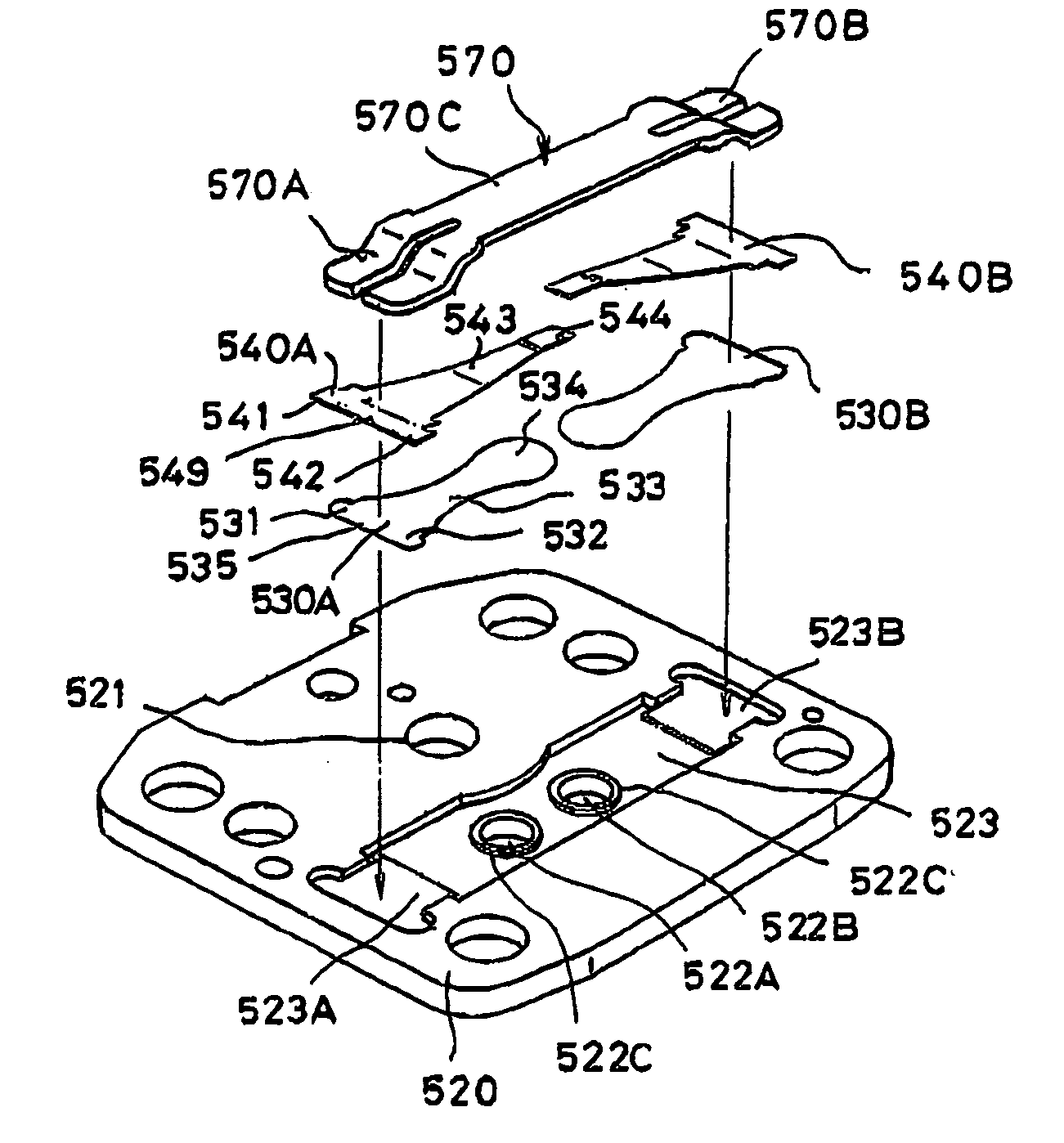
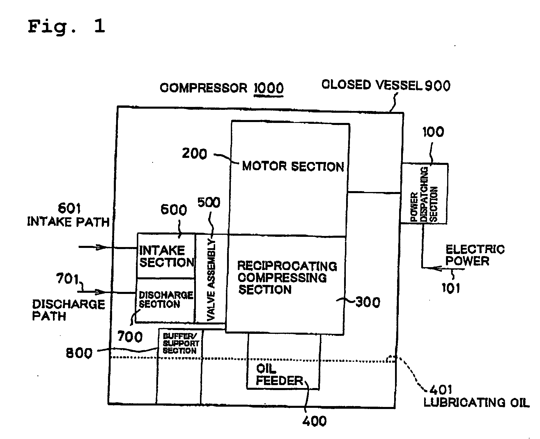
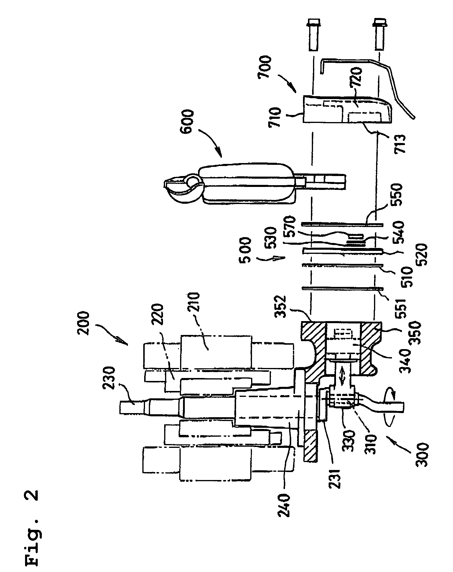
[0032]FIG. 1 is a block diagram showing an entire construction common to both a reciprocating compressor according to an embodiment of the present invention, FIG. 2 is a sectional view showing an entire construction of the embodiment of the present invention in an exploded state, FIG. 3 is a perspective view partly in section, showing an entire construction in an assembled state of various constituent portions, FIG. 4 is an enlarged diagram showing principal portions of FIG. 2 in detail, FIG. 5 is an explanatory diagram showing an assembled state of various portions related to a valve assembly used in the embodiment of the present invention, FIG. 6(A) is an explanatory plan view showing an assembled state of various portions related to the valve assembly in the embodiment of the present invention, FIG. 6(B) is an e...


PUM


Abstract

A reciprocating compressor is disclosed which has a valve construction using plural discharge ports, plural reed valves and plural valve backers to lower the discharge resistance and improve the compression efficiency. The reciprocating compressor (1000) has within a closed vessel (900) a reciprocating compressing section (300) for compressing a required fluid, the reciprocating compressing section (300) comprising a discharge unit for discharging the fluid and a valve assembly (500) for opening and closing the discharge unit, with a plurality of discharge ports (522A, 522B) being formed in the valve assembly, the valve assembly (500) comprising valve members (560), the valve members (560) comprising reed valves (530A, 530B) disposed correspondingly to the discharge ports (522A, 522B) and valve backers (540A, 540B) disposed respectively on back sides of the reed valves, a valve seat (520) having a recess for receiving the valve members therein, and valve members fixing means for urging end sides of the valve members to fix the valve members elastically to fixing portions (523A, 523B) of the recess.

Description

BACKGROUND OF THE INVENTION [0001] 1. Field of the Invention [0002] The present invention relates to a reciprocating compressor to be used, for example, for compressing a refrigerant in a home refrigerator. Particularly, the present invention is concerned with an improvement of a valve assembly portion which is for opening and closing a discharge unit in a compressing section. [0003] 2. Description of the Prior Art [0004] A reciprocating compressor of this type has such a schematic construction as FIG. 1 which illustrates a compressor 1000. [0005] In FIG. 1, the compressor 1000 comprises an assembly. According to the construction of this assembly, a motor section 200 is driven by electric power fed from a power dispatching section 100 which supplies electric power 101. A reciprocating compressing section 300 is connected to the motor section 200 to compress a refrigerant fluid which is introduced from an intake path 601 in an intake section 600 through a valve assembly 500. The refr...

Claims


Application Information

Patent Timeline
IPC IPC(8): F04B39/10
CPCF04B39/1073
Inventor TSUKAMOTO, HIDEAKIWATANABE, RYUJIOHYAMA, TSUYOSHI
Owner SANYO ELECTRIC CO LTD
Why Eureka
Try Eureka