Fuel cell system

a fuel cell and system technology, applied in the field of fuel cell systems, can solve the problems of low energy efficiency of the system, complex system, and widespread beli

Inactive Publication Date: 2007-10-04
GENERAL ELECTRIC CO
View PDF11 Cites 13 Cited by
  • Summary
  • Abstract
  • Description
  • Claims
  • Application Information

AI Technical Summary

Benefits of technology

[0008] Accordingly, there is a need to develop an improved fuel cell system that enables utilization of liquid carrier storage of hydrogen without requiring in...

Problems solved by technology

Accordingly, it is widely assumed that the most practical applications would require the hydrogen storage tank to release hydrogen at about the same temperature that the fuel cell operates at, for example with PEM fuel cells, this temperature range would be from about 60° C. to about 80° C., and widely assumed to be less than 100° C. It is widely believed that the energy efficiency of the system will be lower, and the system will be more complex, if extra heat must be independe...

Method used


Image

  • Fuel cell system
  • Fuel cell system
  • Fuel cell system

Examples


Embodiment Construction

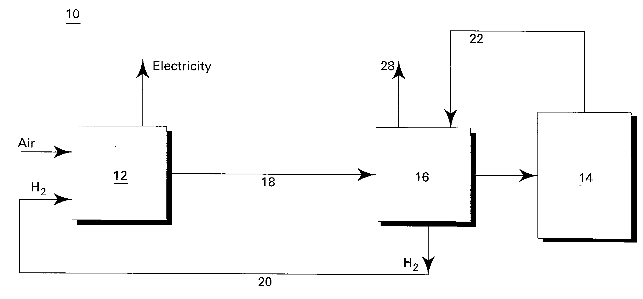
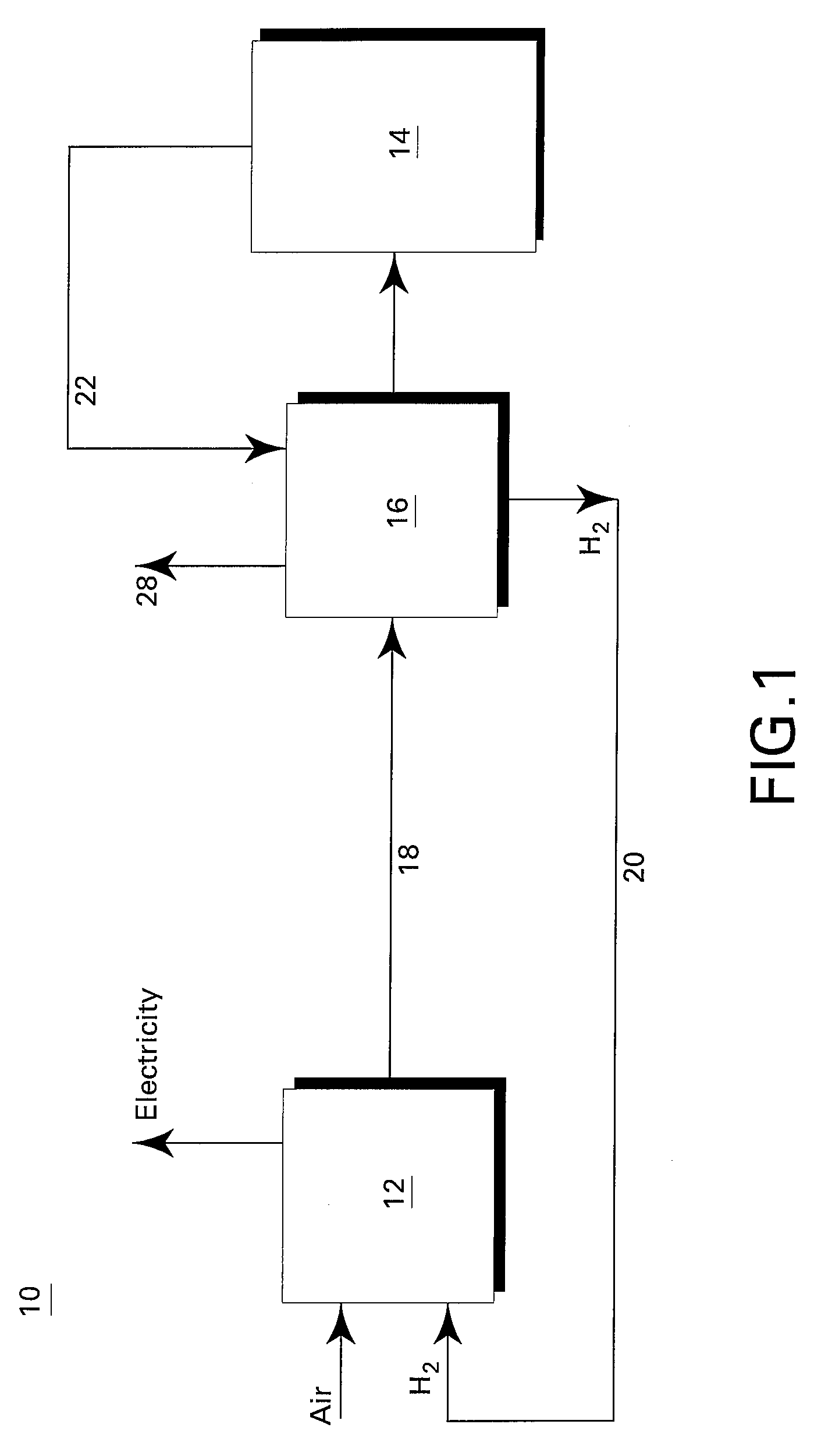
[0018] A fuel cell system 10 comprising a fuel cell 12, a liquid storage tank 14 and a catalyst reactor 16 is shown in FIG. 1. Typically, fuel cell 12 is a PEM fuel cell. As shown hydrogen (H2) and air electrochemically react within fuel cell 12 to produce electricity and an exhaust 18. The exhaust 18 is typically used to heat the reactor 16 and the catalyst to a temperature suitable to dehydrogenate hydrogen 20 from a hydrogen-charged liquid 22 that is fed into the reactor 16 from the liquid storage tank 14. The exhaust 18 typically consists of water in the form of steam or moisture, nitrogen, and small quantities of hydrogen. After heating the reactor 16 and the catalyst, the remaining exhaust 28 vents outside of the system. Fuel cell system 10 is suited for many applications, especially for powering an automobile or other vehicles.

[0019] As discussed above, a significant challenge associated with implementing fuel cell system 10 into an automobile is the temperature required to ...


PUM


Abstract

A fuel cell system comprises a hydrogen storage system for storing and releasing hydrogen, a fuel cell in fluid communication with the hydrogen storage system for receiving released hydrogen from the hydrogen storage system and for electrochemically reacting the hydrogen with an oxidant to produce electricity and an anode exhaust. A catalytic combustor is in fluid communication with the fuel cell for receiving the anode exhaust and for catalytically reacting the anode exhaust to produce an offgas having an elevated temperature that is greater than the temperature of the anode exhaust. The heat from the offgas is used to release the hydrogen from the hydrogen storage system.

Description

CROSS REFERENCE TO RELATED APPLICATIONS [0001] This application is related to co-pending U.S. patent application Ser. No. 11 / 193,970, having docket number 183593-1 and entitled “Fuel Cell System,” U.S. patent application Ser. No. 11 / 292,583, having docket number 183593-2 and entitled “Fuel Cell System,” U.S. patent application Ser. No. 11 / 292,584, having docket number 183593-3 and entitled “Fuel Cell System,” each of which are herein incorporated by reference.BACKGROUND [0002] This invention relates generally to fuel cell systems and more specifically to catalytically combusting an anode exhaust of a fuel cell, for example a Proton Exchange Membrane (PEM) fuel cell, to provide the heat to release hydrogen from a liquid storage material. [0003] Fuel cells, for example PEM fuel cells, are touted as the future of the automotive industry. Fuel cells electrochemically react a fuel, such as hydrogen, with an oxidant, such as air, to produce electricity and water. PEM fuel cells are ideall...

Claims


Application Information

Patent Timeline
IPC IPC(8): H01M8/06H01M8/04
CPCC01B3/26Y02T90/32C01B2203/0405C01B2203/066C01B2203/0822C01B2203/0827C01B2203/0833C01B2203/085C01B2203/0883C01B2203/1041C01B2203/107C01B2203/1252C01B2203/148C01B2203/1685C01B2203/1695H01M8/04022H01M8/04201H01M8/04216H01M8/04268H01M8/0612H01M8/0631H01M2008/1095H01M2250/20Y02E60/50C01B2203/0277Y02T90/40Y02P20/10
Inventor ZHAO, JI-CHENGLIU, KE
Owner GENERAL ELECTRIC CO
Why Eureka
Try Eureka