Heat exchanging system of battery pack using thermoelectric element

Active Publication Date: 2007-10-04
LG ENERGY SOLUTION LTD
View PDF2 Cites 11 Cited by
  • Summary
  • Abstract
  • Description
  • Claims
  • Application Information

AI Technical Summary

Benefits of technology

[0019] In a preferred embodiment, the air inlet port and the air outlet port are adjacent to each other while the Peltier element is interposed between the air inlet port and the air outlet port. More preferably, the first and second heat conduction members are attached to opposite major surfaces of the Peltier element, and first heat conduction member is located inside the air inlet port, whereas the second heat conduction member is located inside the air outlet port. In the heat exchange system with the above-stated construction, the second heat conduction member is located inside the air outlet port, unlike the previously described embodiment of the present invention in which the second heat conduction member is located outside the air inlet port. Consequently, the overall size of the heat exchange system is greatly reduced. Also, air passes through both the first heat conduction me

Problems solved by technology

One of the biggest problems caused from vehicles using fossil fuel, such as gasoline and diesel oil, is creation of air pollution.
In such a high-output, large-capacity secondary battery, however, a large amount of heat is generated from the unit cells during the charge and the discharge of the unit cells.
When the heat generated from the unit cells during the charge and the discharge of the unit cells is not effectively removed, heat is accumulated in the unit cells with the result that the unit cells are degraded.
However, the mounting of the heat dissipating fins at the respective battery cells or the attachm

Method used


Image

  • Heat exchanging system of battery pack using thermoelectric element
  • Heat exchanging system of battery pack using thermoelectric element
  • Heat exchanging system of battery pack using thermoelectric element

Examples


Example

[0027] Now, preferred embodiments of the present invention will be described in detail with reference to the accompanying drawings. It should be noted, however, that the scope of the present invention is not limited by the illustrated embodiments.

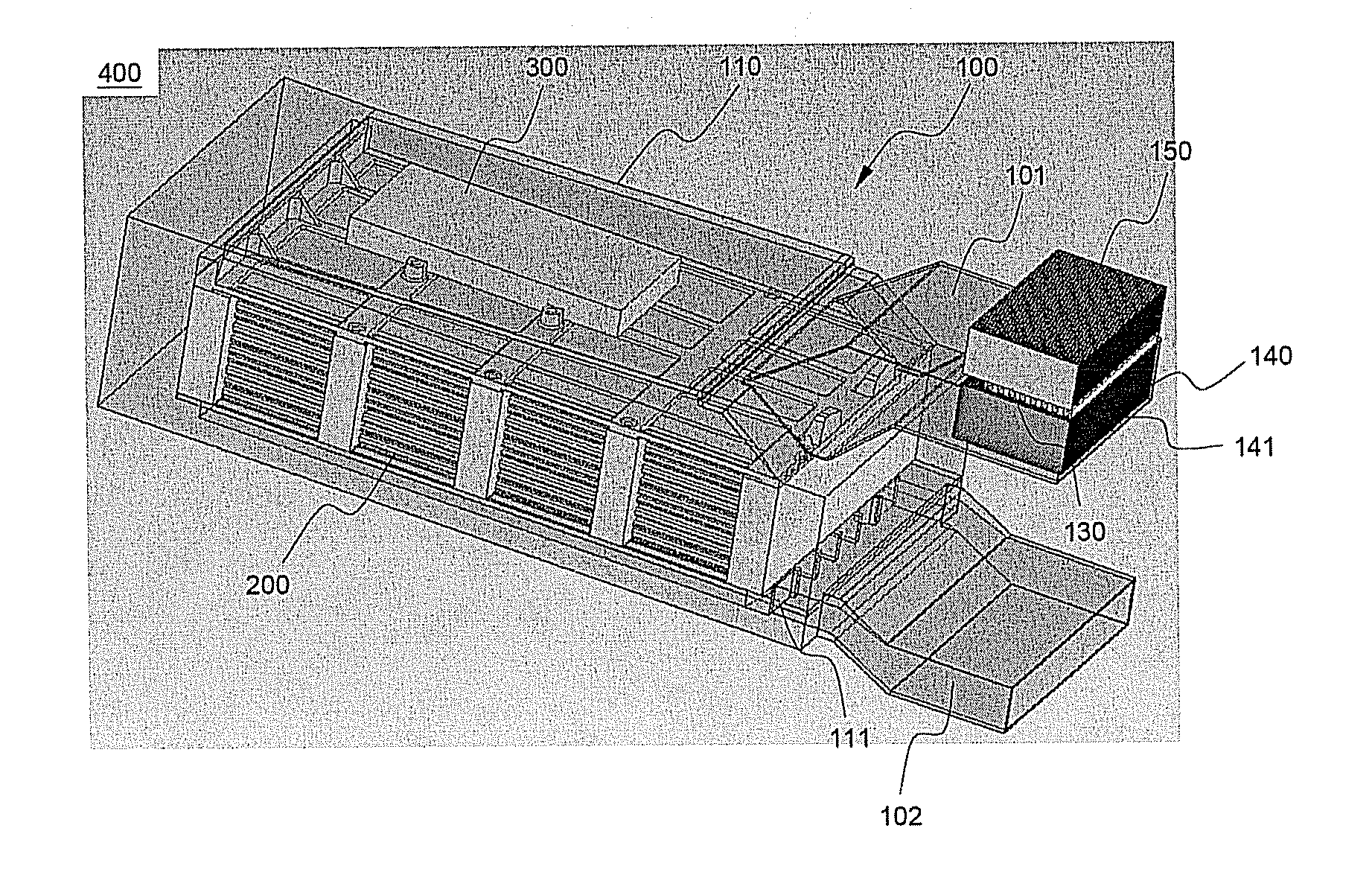
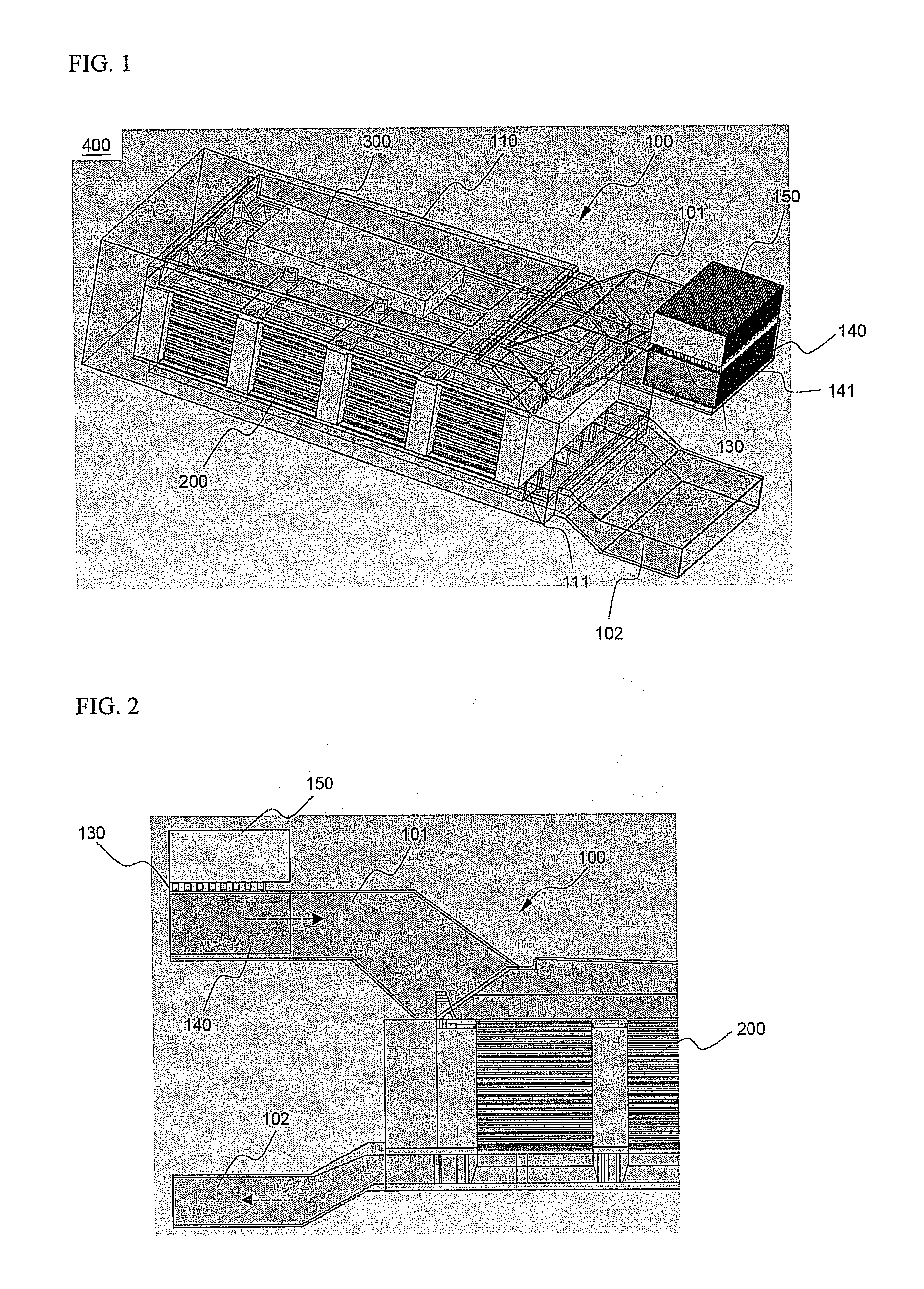
[0028]FIG. 1 typically illustrates a battery system including a heat exchange system according to a preferred embodiment of the present invention. For easy understanding of the drawing, most parts of the battery system are shown as a see-through view.

[0029] Referring to FIG. 1, a battery system 400 is constructed in a structure in which a battery pack 200 and a control unit 300 are mounted in a heat exchange system 100. The battery pack 200 is constructed in a structure in which a plurality of pouch-shaped batteries, as unit cells, are stacked one on another, and are then mounted to a sheathing member, such as a cartridge or a frame, while the batteries are electrically connected with each other. The operation of the battery pack 200 is c...


PUM


Abstract

Disclosed herein is a heat exchange system for battery packs, which controls the temperature of a medium- or large-sized battery pack including a plurality of unit cells such that the battery pack can be operated under the optimum operating conditions. The heat exchange system includes an air inlet port and an air outlet port formed at one side of a housing surrounding the outer surface of the battery pack so as to form a predetermined flow channel, through which air flows, a driving fan mounted in the flow channel for driving the air to flow through the flow channel, and a Peltier element mounted at the air inlet port for controlling the temperature of air introduced into the air inlet port. In the heat exchange system according to the present invention, the thermoelectric element is mounted inside the air inlet port, through which air for cooling the battery pack is introduced into the heat exchange system. Consequently, the present invention has the effect of easily controlling the optimum operating temperature of the battery pack, reducing influences caused by external conditions, and decreasing noise and vibration.

Description

FIELD OF THE INVENTION [0001] The present invention relates to a heat exchange system that is capable of controlling the temperature of a medium- or large-sized battery pack including a plurality of unit cells such that the battery pack can be operated under the optimum operating conditions, and, more particularly, to a heat exchange system for battery packs, which controls the temperature of a medium- or large-sized battery pack including a plurality of unit cells such that the battery pack can be operated under the optimum operating conditions, wherein the heat exchange system includes an air inlet port and an air outlet port formed at one side of a housing surrounding the outer surface of the battery pack so as to form a predetermined flow channel, through which air flows, a driving fan mounted in the flow channel for driving the air to flow through the flow channel, and a Peltier element mounted at the air inlet port for controlling the temperature of air introduced into the air...

Claims


Application Information

Patent Timeline
IPC IPC(8): H01M10/50
CPCH01M10/345H01M10/5004H01M10/5006H01M10/5016H01M10/5085H01M10/5032H01M10/5071H01M10/5073H01M10/502H01M10/625H01M10/63H01M10/615H01M10/647H01M10/6572H01M10/6565H01M10/6566H01M10/613Y02E60/10H01M50/20
Inventor PARK, JONGMINYOON, JUNILLYANG, HEEKOOKNAMGOONG, JOHN E.AHN, JAESUNGWOO, HYOSANG
Owner LG ENERGY SOLUTION LTD
Why Eureka
Try Eureka