
Electric connector

a technology of electric connectors and connectors, applied in the direction of coupling device connections, coupling contact members, electrical apparatus, etc., can solve the problems of increasing the number of components, affecting the quality of electrical connections, and the failure of good connection to the mating connectors, etc., to achieve the effect of simple production, easy connection with the electric wire, and easy production

Inactive Publication Date: 2007-10-04
MEA TECH PTE
View PDF3 Cites 22 Cited by
  • Summary
  • Abstract
  • Description
  • Claims
  • Application Information

AI Technical Summary

Benefits of technology

[0019]The invention has the above configurations to exert the following excellent effects. According to the first aspect of the invention, in the plug terminal, before coupling the electric connector to the mating connector, the contact portion is held and pushed in the connector housing by the gate member while the spring is compressed. Therefore, unlike the related art, the contact portion can be protected with the simple structure while the cover body is not moved. Because the spring is integrally provided in the plug terminal, the number of component items is not increased, there is no possibility that the contact failure is caused between the contact portion and the spring like the related art, and the contact portion and the spring are easily assembled into the connector housing.
[0021]According to the third aspect of the invention, the contact portion is provided at one end of the connected laterally-facing S-shaped spring units, and the fixing portion and the electric wire connecting portion are provided at the other end. Therefore, unlike the related art, the contact portion and the spring can be integrated. The plug terminal can easily be produced by blanking the electroconductive metal plate.
[0022]According to the fourth aspect of the invention, the two types of first and second plug terminals can simply be produced by changing the forming positions of the electric wire connecting portions to the fixing portion. When the first and second plug terminals are alternately fitted in the connector housing, the positions of the electric wire connecting portions provided in the first and second plug terminals do not overlap each other in the adjacent plug terminals, and the gap between the electric wire connecting portions is broadened. Therefore, the connection with the electric wire becomes easy and the short circuit trouble between the terminals can be decreased.
[0023]According to the fifth aspect of the invention, the gate member can include the holding means for accommodating and holding the contact portion of the plug terminal and the operating member which releases the hold of the holding means in fitting and coupling the electric connector to the mating connector. Therefore, the gate member by which the projection and accommodation of the plug terminal are operated with a simple structure can be formed.
[0025]According to the seventh and eighth aspects of the invention, in coupling the electric connector to the mating connector, the coupling can be locked by providing the lock member in the connector housing. The connector housing is covered with the cover body, and the housing and the cover body are individually formed. Therefore, the shape of the housing is not complicated, and the assembly in which the spring is fitted is simplified.
[0026]According to the ninth aspect of the invention, the lock can easily be released between the electric connector and the mating connector by providing the operating means in the cover body.

Problems solved by technology

Therefore, the obstacle or the like comes into contact with the projected plug terminal to damage or deform the plug terminal, and the plug terminal might be folded down at worst.
Any damage, deformation or the like of the plug terminal causes a failure of connection to the mating connector in good condition.
However, in the terminal portion 38 of the electric connector 35, because the plug terminal 37 and the spring 36 are individually formed, the number of component items is increased while an assembling work becomes complicated, and it is difficult to stably maintain electric contact between the plug terminal 37 and the spring 36.

Method used


Image

  • Electric connector
  • Electric connector
  • Electric connector

Examples


first embodiment

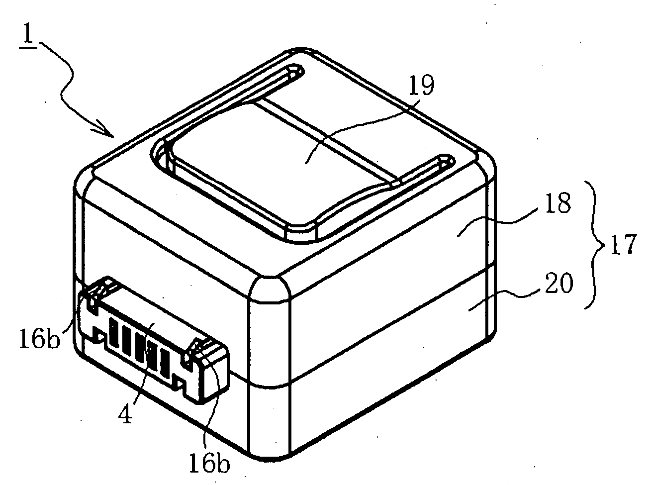
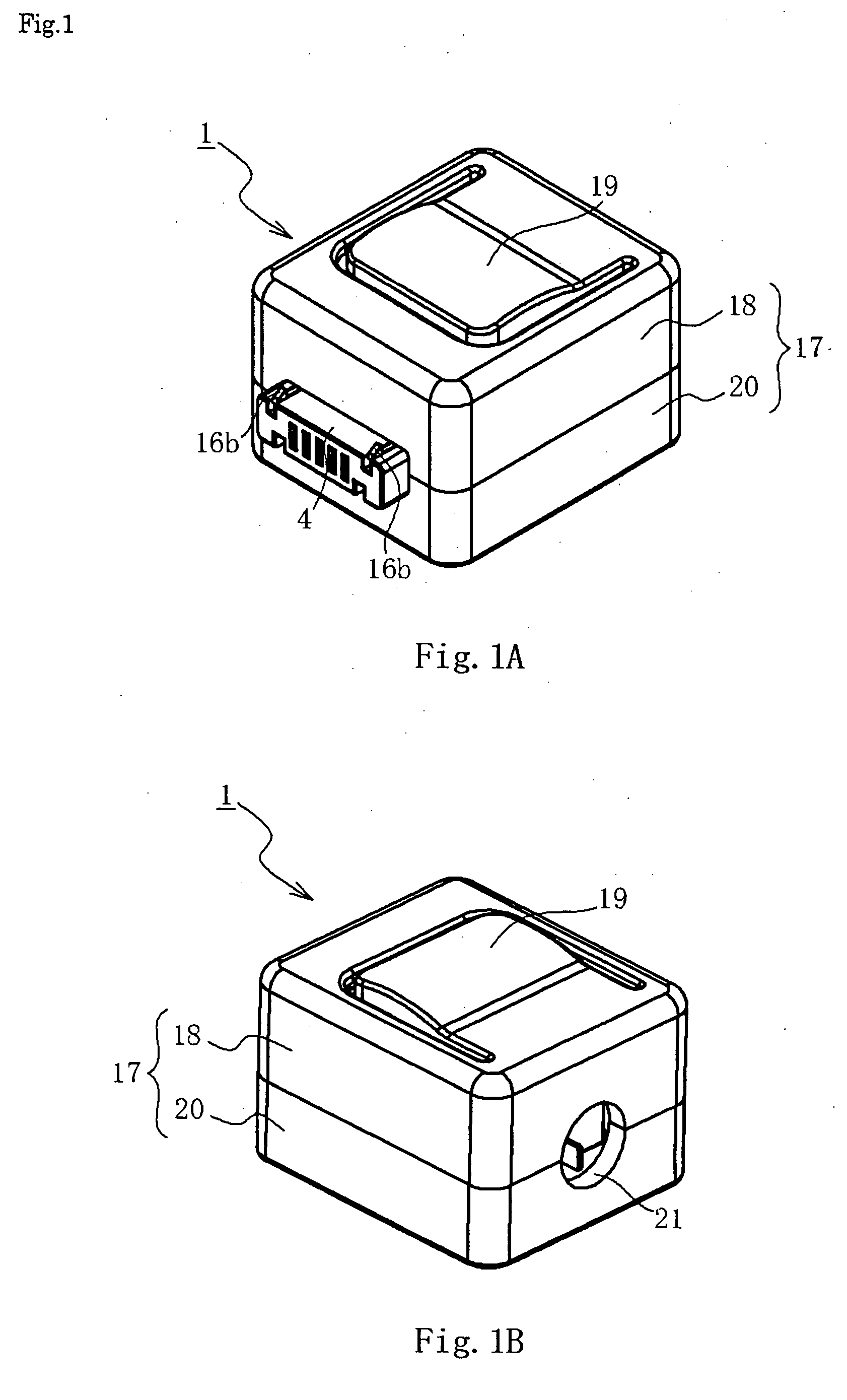
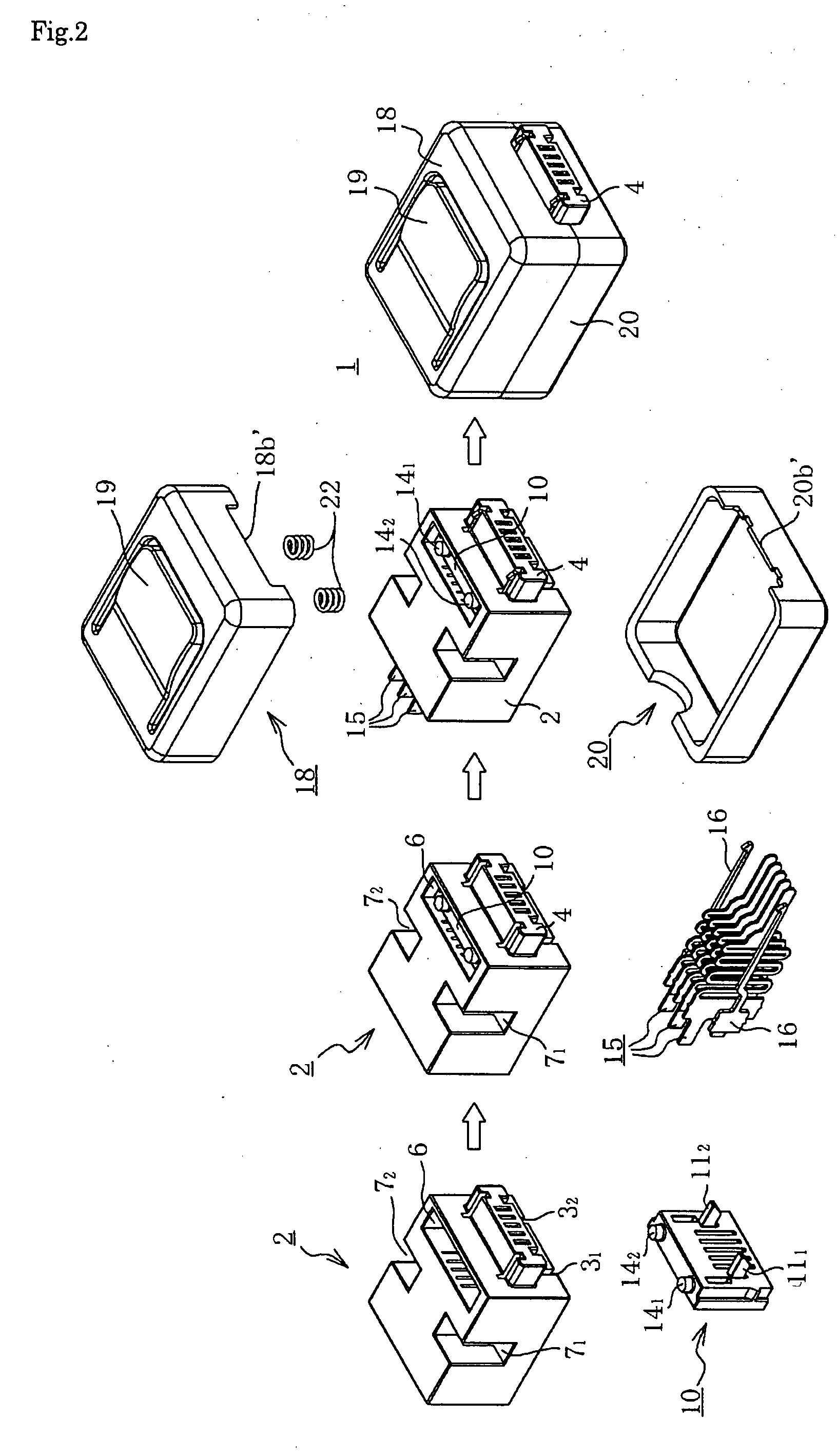
[0041]FIG. 1 shows an electric connector according to a first embodiment of the invention, FIG. 1A is an appearance perspective view when viewed from one direction, and FIG. 1B is an appearance perspective view when viewed from the other direction. FIG. 2 is an appearance perspective view showing a process of assembling the electric connector of FIG. 1. FIG. 3 shows a connector housing of the electric connector of FIG. 1, FIG. 3A is an appearance perspective view, FIG. 3B is a rear view when viewed from an X1 direction of FIG. 3A, and FIG. 3C is a front view when viewed from an X2 direction of FIG. 3A. FIG. 4 shows a gate member of the electric connector of FIG. 1, FIG. 4A is an appearance perspective view, FIG. 4B is a rear view when viewed from an X3 direction of FIG. 4A, and FIG. 4C is a side view when viewed from an X4 direction of FIG. 4A. FIG. 5 shows a plug terminal of the electric connector of FIG. 1, FIG. 5A is a side view showing one type of plug terminal, and FIG. 5B is a...


PUM


Abstract

An electric connector includes a plug terminal 15 and a connector housing 2. The plug terminal 15 has a contact portion 151 in one end and an electric wire connecting terminal 153 in the other end, and the connector housing 2 accommodating the plug terminal. In the plug terminal 15, the contact portion and the electric wire connecting portion are connected through an elastic spring portion 15b, the connector housing 2 accommodates both the plug terminal 15 and a gate member 10 which holds a contact portion of the plug terminal, the contact portion 151 of the plug terminal is held in the connector housing by the gate member 10 while the spring is compressed and pushed in, and the hold state is released to project the contact portion of the plug terminal from the connector housing in coupling the electric connector to the mating connector. Therefore, the invention can provide the electric connector enabling it to protect the plug terminal with a simple structure in which the contact portion of the plug terminal is pushed in the connector housing before coupling the electric connector to the mating connector.

Description

BACKGROUND OF THE INVENTION[0001]1. Field of the Invention[0002]The present invention relates to a plug-type electric connector coupled to a receptacle connector.[0003]2. Description of the Related Art[0004]An electric connector is used in almost all of electric or electronic instruments. The electric connector usually includes a receptacle connector and a plug-type connector which is plugged in the receptacle connector. For example, as shown in FIG. 12, a plug-type electric connector 30 disclosed in U.S. Pat. No. 6,896,529B2 includes three plug terminals 31a to 31c, a connector housing (hereinafter simply referred to as “housing”) 32, and a cover body 33. The housing 32 accommodates the plug terminals, and the housing 32 is covered with the cover body 33. The housing 32 and the cover body 33 are made of insulating materials.[0005]The housing 32 includes a rectangular solid-shaped body 32a and a U-shaped heads 32b extending from the body 32a. Three plug terminals 31a to 31c are proj...

Claims


Application Information

Patent Timeline
Patent Type & Authority Applications(United States)
IPC IPC(8): H01R13/24
CPCH01R13/2428H01R13/633H01R13/6275H01R13/04H01R13/02
Inventor HONG, FAN SHIN
Owner MEA TECH PTE
Features
  • Generate Ideas
  • Intellectual Property
  • Life Sciences
  • Materials
  • Tech Scout
  • Unparalleled Data Quality
  • Higher Quality Content
  • 60% Fewer Hallucinations
Learn More