

Superconducting tunable filter
a tunable filter, superconducting technology, applied in the direction of waveguides, basic electric elements, waveguide type devices, etc., can solve the problems of poor power durability, high susceptibility to shaking or vibration, slow response speed, etc., and achieve the effect of satisfactory power characteristics, simple and novel structure of transmission filters
- Summary
- Abstract
- Description
- Claims
- Application Information
AI Technical Summary
Benefits of technology
Problems solved by technology
Method used
Image

Examples
example 1
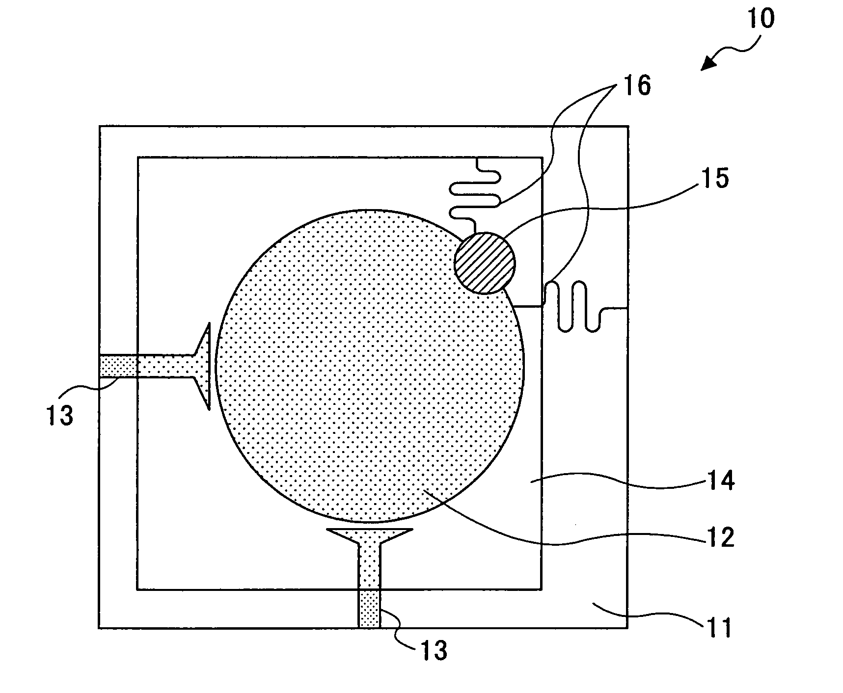
[0057] A 20×20×0.5 [mm] MgO single-crystal plate is used as the dielectric base plate 11 of the superconducting filter 10. A disk-shaped superconducting resonator pattern 12, a bias application hairpin wiring 16 extending from the resonator pattern 12, and input / output feeders 13 are formed on the MgO dielectric base plate 11 by epitaxial growth of a YBCO thin film and a patterning process. The diameter and the thickness of the superconducting resonator pattern 12 are 128 mm and 0.5 μm, respectively. A ground electrode (ground film) is also formed on the back face of the MgO dielectric base plate 11 by epitaxial growth of a YBCO thin film.
[0058] A BZN plate is used as the top dielectric 14, and is placed on the YBCO patterned face of the MgO dielectric base plate 11. On the top face of the BZN plate are formed in advance a dual-mode producing conducting pattern 15 with a diameter of 38 mm and a bias application hairpin wiring 16.
[0059] This superconducting filter 10 has a center c...
example 2
[0060] As in the first example, a disk-shaped superconducting resonator pattern 12, a bias application hairpin wiring 16 extending from the resonator pattern 12, and input / output feeders 13 are formed on a 20×20×0.5 [mm] MgO single-crystal plate 11. The diameter and the thickness of the disk resonator 12 are 128 mm and 0.5 μm, respectively.
[0061] A (Ba, Sr)TiO3 thin film is formed by epitaxial growth over the dielectric base plate 11. A YBCO thin film is formed over the (Ba, Sr)TiO3 film by epitaxial growth, and patterned into a dual-mode producing conducting pattern 15 with a diameter of 38 mm and a hairpin wiring 16 for bias application.
[0062] This superconducting filter 10 has a center carrier frequency at 3.90 GHz without application of a bias voltage. Upon application of 30 V bias, the center carrier frequency shifts to 4.10 GHz. A 0.2 GHz change is achieved.
[0063] In this manner, in the first embodiment, the permittivity of the top dielectric 14 with a dual-mode producing c...
PUM
 Abstract
Description
Claims
Application Information