Bone fixation assembly

a technology for fixing parts and parts, applied in the direction of sheets, screws, nuts, etc., can solve the problem of blocking the rotation ability of sleeves

Inactive Publication Date: 2007-10-04
SPHEROFIX
View PDF8 Cites 46 Cited by
  • Summary
  • Abstract
  • Description
  • Claims
  • Application Information

AI Technical Summary

Benefits of technology

[0006]The present invention has the goal of eliminating the aforementioned problems and drawbacks during joining and fixing of two elements to each other, for

Problems solved by technology

With the pressure that is exerted against the screw, it presses the sleeve down into the implant plate's lower hole, where it is wedged and therefore blocks the sle

Method used


Image

  • Bone fixation assembly
  • Bone fixation assembly
  • Bone fixation assembly

Examples


Embodiment Construction

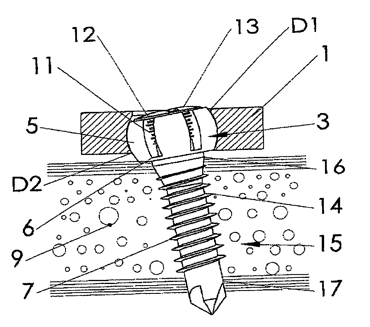
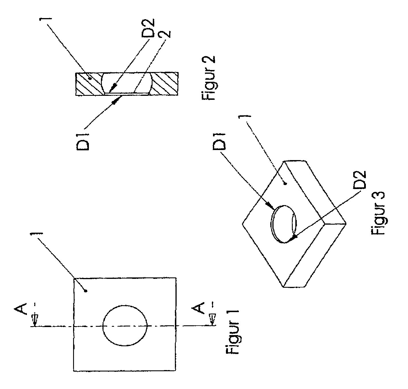
[0023]FIGS. 1 and 2 show an implant plate 1 in an arrangement according to the present invention, referred to as a plate below, made of a hard, machinable material, preferably metal. The plate can have varying thickness—for example, it can vary from about 2 mm and up. The plate 1 has a spherical through hole 2, which is drilled in plate 1, so that the center of the sphere of hole 2, seen from above, is shifted downward and therefore asymmetrically positioned in the plate, so that the upper hole opening of hole 2 has a diameter D1 that is less than the diameter D2 of the lower hole opening of hole 2.

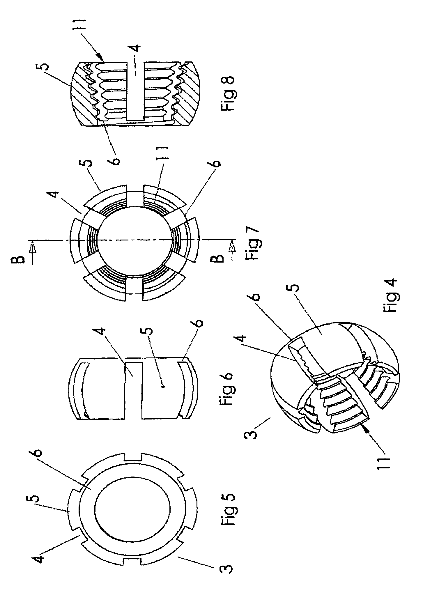
[0024]FIGS. 3, 4, 5, 6, 7 and 8 show a sleeve 3, made of a suitable material, preferably also metal, spherical in shape with flanges 5 bounded by slotted groove 4, with a remaining thin connection 6 between the flanges 5. This connection, in the form of a ring 6, permits the flanges 5 to be elastically deformed, so that the sleeve 3 can be clamped into the spherical hole 2 of plate 1. The...


PUM


Abstract

The present invention pertains to an arrangement, as well as a method, for fastening and fixing of first element, in the form of an implant, against the second element, in the form of bone tissue, during surgical use of a screw joint, by means of a screw with a conical head with a cone toward the screw tip, said head having an outside thread with a small pitch, which is intended to be screwed into the implant, and a main thread on the stem of the screw, which has greater pitch than the thread of the screw head, and said thread is intended to be screwed into the bone tissue, in which said first element, the implant, has a spherical hole, in which a ductile sleeve is arranged in the form of a sleeve divided into segments, flanges, and has a spherical shape that matches the spherical shape of hole, and said sleeve has a conical threaded inside shape that is complementary to the outer threaded shape of the screw head, in which screw, when tightened, can fasten the implant in any desired angle, relative to the other element, and fix the screw joint in this position.

Description

TECHNICAL AREA OF THE INVENTION[0001]The present invention concerns an arrangement, for example, during surgical use of a screw joint for fastening and fixing a first element, for example, in the form of an implant or a combination implant, against another element, for example, in the form of bone tissue, by means of a screw containing, on the one hand, a conical head with a cone toward the screw tip, said head having an outside thread with a small pitch, which is intended to be screwed into the first element, for example, the implant; and, on the other hand, a main thread on the screw's stem, which has greater pitch than the pitch of the screw head and is intended to be screwed into the other element, for example, the bone tissue, said screw being fastenable at a desired angle relative to the element and fixed in this position.TECHNICAL BACKGROUND OF THE INVENTION[0002]There are many different solutions and methods for fastening elements to each other. The use of traditional screws...

Claims


Application Information

Patent Timeline
IPC IPC(8): A61F2/30
CPCA61B17/8047A61B17/8057A61B17/8605A61B2017/868A61C8/005A61C8/0053F16B43/02A61C8/0069F16B5/02F16B35/048F16B35/06F16B37/00A61C8/0066A61B17/8685A61C8/0018F16B5/025
Inventor OLERUD, SVEN
Owner SPHEROFIX
Why Eureka
Try Eureka