Al technical title is built by PatSnap Al team. It summarizes the technical point description of the patent document.
a bone and bone technology, applied in the field of osteoplasty procedures, can solve the problems of fractures in the spine and hips, affecting mobility and quality of life, and the medical advances aimed at slowing or arresting bone loss from aging have not provided solutions to this problem
Inactive Publication Date: 2007-10-04
DFINE INC
View PDF94 Cites 24 Cited by
Summary
Abstract
Description
Claims
Application Information
AI Technical Summary
This helps you quickly interpret patents by identifying the three key elements:
Problems solved by technology
Method used
Benefits of technology
Problems solved by technology
Medical advances aimed at slowing or arresting bone loss from aging have not provided solutions to this problem.
Osteoporosis affects the entire skeleton but most commonly causes fractures in the spine and hip.
Spinal or vertebral fractures also cause other serious side effects, with patients suffering from loss of height, deformity and persistent pain which can significantly impair mobility and quality of life.
Osteoporosis describes a condition of decreased bone mass that leads to fragile bones which are at an increased risk for fractures.
In an osteoporosis bone, the sponge-like cancellous bone has pores or voids that increase in dimension making the bone very fragile.
In an elderly patient, bone resorption can surpass bone formation thus resulting in deterioration of bone density.
Since the PMMA needs to be is forced into the cancellous bone, the techniques require high pressures and fairly low viscosity cement.
Since the cortical bone of the targeted vertebra may have a recent fracture, there is the potential of PMMA leakage.
Leakage of PMMA during vertebroplasty can result in very serious complications including compression of adjacent structures that necessitate emergency decompressive surgery.
The exothermic reaction of PMMA carries potential catastrophic consequences if thermal damage were to extend to the dural sac, cord, and nerve roots.
Vertebroplasty p
Method used
Image
Click on the blue label to locate the original text in one second.
Reading with bidirectional positioning of images and text.
Examples
Embodiment Construction
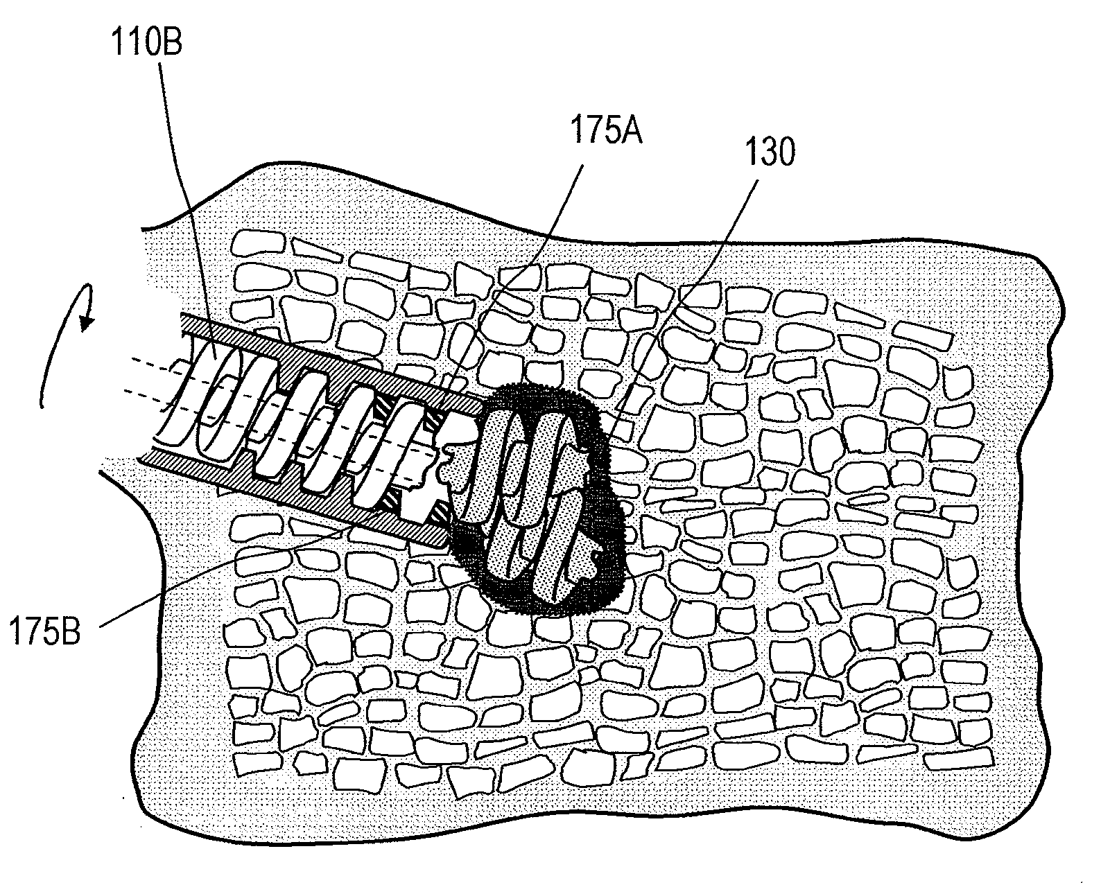
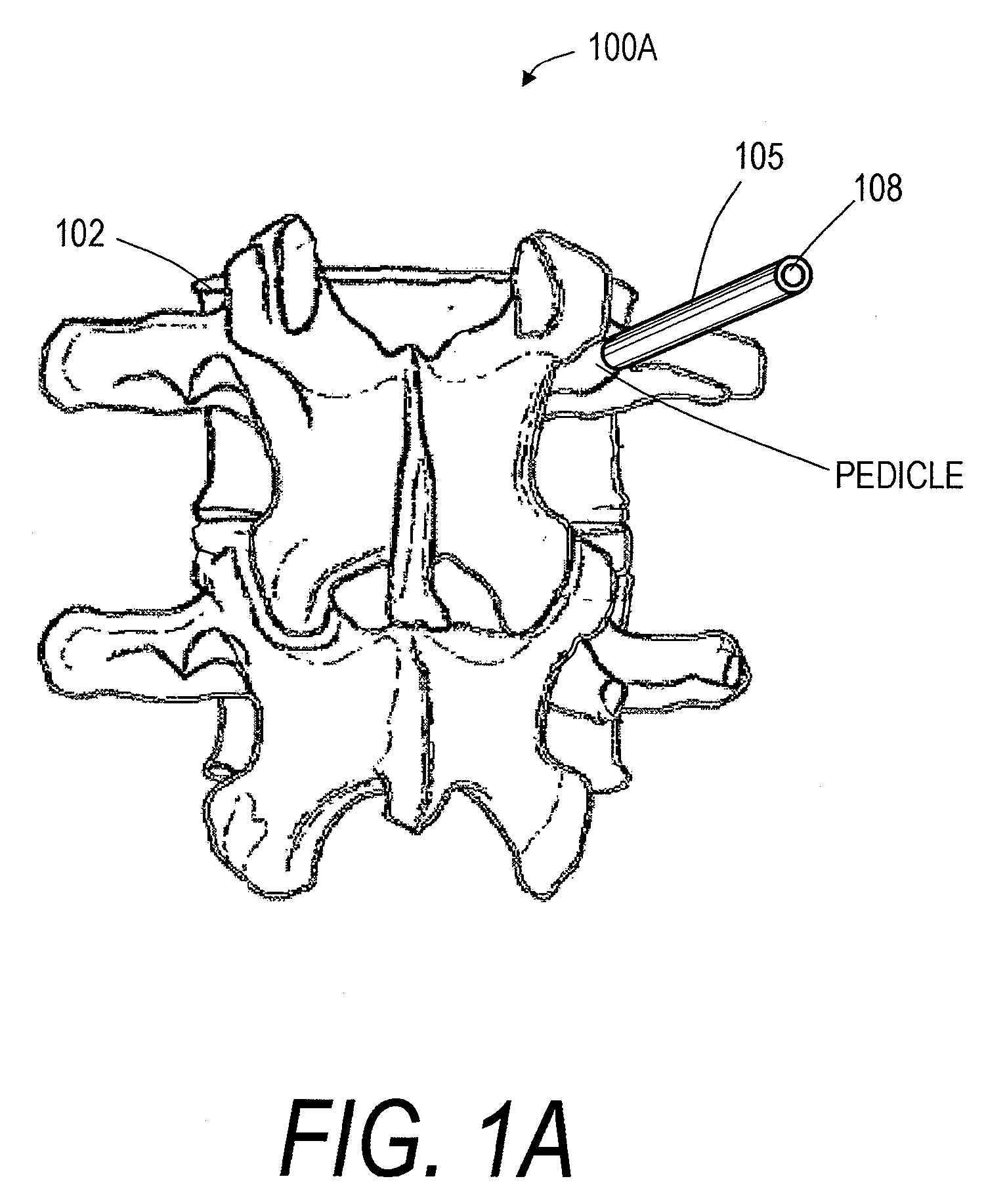
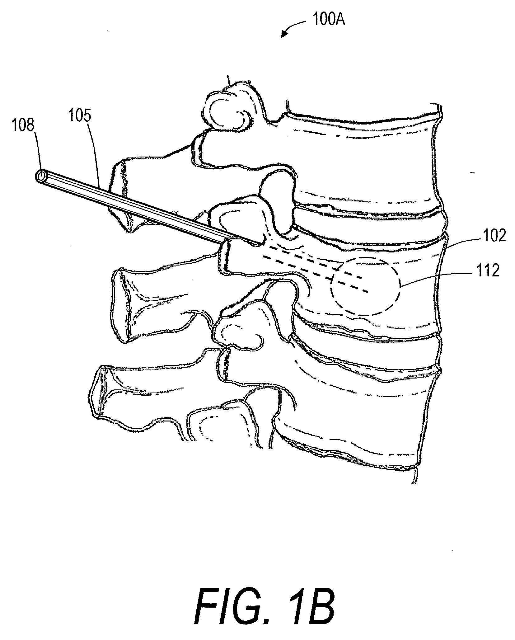
[0043]Referring to FIGS. 1A and 1B, one embodiment of bone fill introducer or injector system 100A is shown that is configured for treatment of an abnormal vertebra 102 such as in the case of a vertebral compression fracture. Introducer system 100A as in FIGS. 2A-C includes introducer sleeve 105 with passageway 108 therein that is configured for the introduction of an elongated implant body 110A therethrough to a targeted site 112 in a vertebra (see FIGS. 1A-1B). As can be seen in FIG. 2, the elongated implant body 110A has a first configuration that is substantially unyielding along a longitudinal axis 115 of the body. The term “unyielding” as used herein means that the implant body is substantially rigid, inflexible and sufficiently strong to allow the implant to be axially pushed or driven through passageway 108 in the introducer sleeve 105. The implant body is preferably of a polymeric material, a ceramic material, a glass material or a combination thereof that allows transforma...
PUM
Abstract
The present invention relates in certain embodiments to medical devices for treating vertebral compression fractures. In one embodiment, the invention relate to instruments and methods for introducing fill material into a vertebral body that slowly expands vertebral height without explosive balloon expansion as in kyphoplasty. The system provides a fill material that infills a vertebra without flowable bone cement as used in kyphoplasty and vertebroplasty procedures. Thus, the bone fill system prevents the possibility of extravasation of material into the spinal canal which occurs in a significant number of kyphoplasty and vertebroplasty procedures. An energy source can apply energy to a substantially rigid implant material in order to soften, melt, or fracture the implant material to infill a vertebral body.
Description
CROSS-REFERENCE TO RELATED APPLICATIONS[0001]This application claims the benefit under 35 U.S.C. § 119(e) of U.S. Provisional Patent Application No. 60 / 765,852, filed on Feb. 7, 2006. This application is also related to U.S. patent application Ser. No. 11 / 165,652, filed Jun. 24, 2005, now U.S. Pub. No. 2006-0122623; U.S. patent application Ser. No. 11 / 165,651, filed Jun. 24, 2005, now U.S. Pub. No. 2006-0122622; U.S. patent application Ser. No. 11 / 208,448, filed Aug. 20, 2005, now U.S. Pub. No. 2006-0122621; U.S. patent application Ser. No. 11 / 469,764, filed Sep. 1, 2006; U.S. application Ser. No. 11 / 209,035, filed Aug. 22, 2005, now U.S. Pub. No. 2006-0122625; U.S. application Ser. No. 11 / 196,045, filed Aug. 2, 2005, now U.S. Pub. No. 2006-0122624; and U.S. application Ser. No. ______, filed Feb. 7, 2007 (Atty. Docket No. DFINE.031A2) and titled “SYSTEMS FOR TREATING BONE.” The entire contents of all of the above applications are hereby incorporated by reference and should be consi...
Claims
Application Information
Patent Timeline
Application Date:The date an application was filed.
Publication Date:The date a patent or application was officially published.
First Publication Date:The earliest publication date of a patent with the same application number.
Issue Date:Publication date of the patent grant document.
PCT Entry Date:The Entry date of PCT National Phase.
Estimated Expiry Date:The statutory expiry date of a patent right according to the Patent Law, and it is the longest term of protection that the patent right can achieve without the termination of the patent right due to other reasons(Term extension factor has been taken into account ).
Invalid Date:Actual expiry date is based on effective date or publication date of legal transaction data of invalid patent.