Roof system

a roof system and roof plate technology, applied in the field of roof plate systems, can solve the problems affecting the performance of the roof plate, so as to improve the uplift strength, eliminate the problem of deterioration of the blocking assembly, and improve the fire rating

Inactive Publication Date: 2007-10-11
GEMBALA HENRY
View PDF16 Cites 5 Cited by
  • Summary
  • Abstract
  • Description
  • Claims
  • Application Information

AI Technical Summary

Problems solved by technology

This currently used roof system, as described above, has several problems.
In particular, wood, by its nature, is subject to rotting and deterioration.
Also, wood blocking is a flammable product and, thus, has an inferior fire rating.
In addition, the use of mechanical fasteners to attach the base sheet creates holes in the light concrete.
This results in weakening of the underlying lightweight insulating concrete deck.
This further compromises the strength of the lightweight concrete by adding additional holes to the lightweight concrete as a result of attachment of the new base sheet fasteners.

Method used


Image

  • Roof system
  • Roof system

Examples


Embodiment Construction

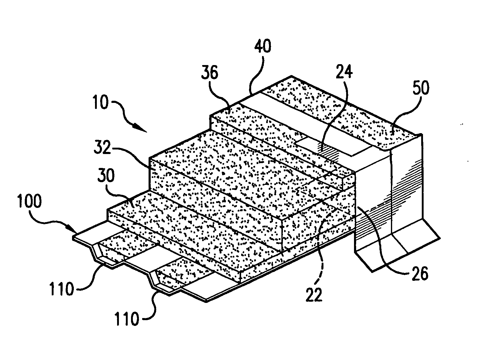
[0017]The roof system of the present invention is shown in FIG. 2 and is generally indicated as 10.

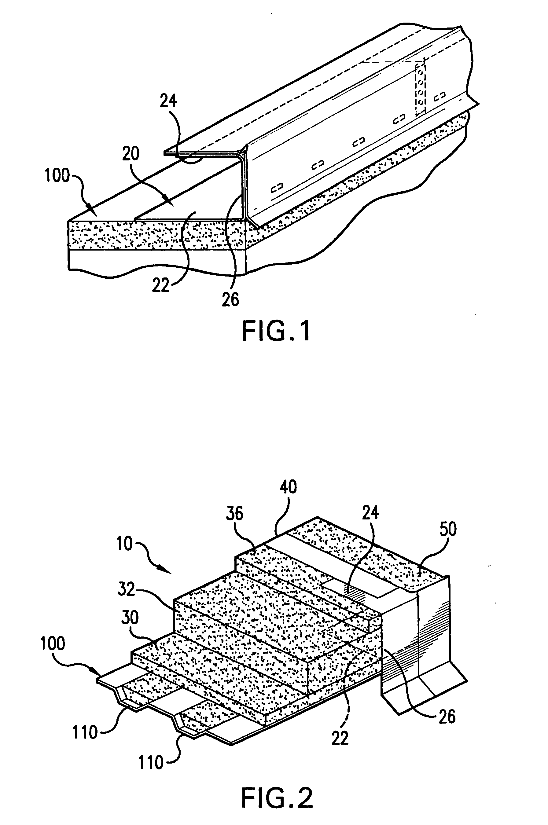
[0018]Referring to FIG. 1, a non-corrosive metal blocking structure is used in the roof system of the present invention and replaces wood blocking of conventional roof systems. In this particular embodiment, the non-corrosive metal blocking structure is a perimeter edge closure 20 that includes an anchoring flange 22 that attaches to the roof deck 100 using industry standards fasteners. The perimeter edge closure 20 also includes and upper flange 24 extending in spaced, parallel relation above the anchoring flange 22, forming a gap or area of depth therebetween. An intermediate flange 26 extends perpendicularly between the upper flange and the anchoring flange along the outer perimeter of the roof.

[0019]Referring now to FIG. 2, the entire assembled components of the roof system 10 are shown in a cross-sectional perspective view. In this particular example, the underlying roof deck 100 ...


PUM


Abstract

A roofing system provides a stronger bond than conventional roof systems to withstand greater uplift pressures in hurricane force winds, while also providing a sound fire rating. The system includes a non-corrosive metal blocking structure, including a perimeter edge closure that has an anchoring flange for attachment to the roof deck, a parallel upper flange and an intermediate flange extending perpendicularly between the upper and lower flanges. The system further includes lightweight insulating concrete applied to the roof deck and filled between the upper and lower flanges of the edge closure, an inter-ply sheet applied by torch or self-adhesive directly to the insulating lightweight concrete, and a torch applied cap membrane over the inter-ply sheet. Direct attachment of the inter-ply sheet to the lightweight insulating concrete without the use of hardware fasteners preserves the integrity of the underlying lightweight insulating concrete for future re-roofing.

Description

[0001]This application is based on provisional patent application Ser. No. 60 / 744,120 filed on Feb. 16, 2006.BACKGROUND OF THE INVENTION[0002]1. Field of the Invention[0003]This invention relates to roofing systems, and, more particularly, to roofing systems that use lightweight insulating concrete with an overlying inter-ply sheet and cap membrane on flat roof areas.[0004]2. Discussion of the Related Art[0005]Currently, the traditional roof system that is used on flat roof areas consists of wood blocking at the perimeter edge of the roof, a lightweight insulating concrete deck, and a base sheet mechanically fastened to the underlying lightweight insulating concrete with the use of fasteners and washers. Once the base sheet has been mechanically attached to the lightweight insulating concrete, a two ply modified roof system is applied to the base sheet. The two ply system uses an inter-ply sheet and a cap membrane and is applied using a torch heat weld or a cold applied adhesive to ...

Claims


Application Information

Patent Timeline
Patent Type & Authority Applications(United States)
IPC IPC(8): E04B7/00
CPCE04D13/1643E04D13/15
Inventor GEMBALA, HENRY
Owner GEMBALA HENRY
Why Eureka
Try Eureka