Fluid processing system

a technology of fluid processing and fluid, which is applied in the direction of manufacturing tools, transportation and packaging, mechanical equipment, etc., can solve the problems of large size of the settling tank needed damage to the pump(s) used, and large amount of fluid to remove the remaining particles, so as to reduce the amount of settling air, facilitate the settling of particles, and reduce the effect of settling

Inactive Publication Date: 2007-10-11
THOMPSON DAVID
View PDF5 Cites 6 Cited by
  • Summary
  • Abstract
  • Description
  • Claims
  • Application Information

AI Technical Summary

Benefits of technology

[0010] The fluid processing system according to the present disclosure can advantageously minimize the creation of entrained air through the use of a variable height weir. The weir can automatically adjust its height so that the fluid flowing thereover and entering into the interior cavity produces little or no entrained air. Additionally, the fluid processing system can advantageously use a cyclonic flow pattern to separate the particles within the fluid. The separated particles can accumulate on the bottom of the interior cavity while the particle free or reduced contaminant fluid flows into the inner chamber to be pumped therefrom. The use of an inner chamber within the interior cavity can advantageously facilitate the settling of the particles out of the fluid and reduce the entrained air within the fluid flowing into the inner chamber. The fluid flow originates from a central portion of the interior cavity and enters into the inner chamber through the open bottom. Within the inner chamber the fluid has additional settling time to allow entrained air to escape and particles to drop therefrom. The tank can have a tapering bottom that funnels the accumulated particles to a central location. The bottom of the tank can be flushed through a flush line to remove the contaminants from within the tank. The contaminants can thereby advantageously be removed without manual cleaning of the tank. Additionally, site gages can be advantageously utilized to visually show the difference between the fluid in the interior cavity and within the inner chamber. Visual comparison can provide an indication of the effectiveness of the fluid processing system.

Problems solved by technology

The debris can damage the pump(s) used to supply the fluid to the working tool(s).
Additionally, the fluid can contain entrained air or gas that can also be detrimental to the pump (e.g., cavitation) and other fluid handling devices used to transport the fluid to the working tools.
The smaller particles, however, can escape past the filters, and, as a result, the fluid may require further processing to remove the remaining particles.
The size of the settling tank needed to remove the particles can be large and can occupy a significant amount of floor space.
This increased level can decrease the effectiveness of the settling tank.
The manual removal is a time consuming and undesirable job.
Additionally, the removal process may require that the entire central cooling system be shut down, thereby idling the working tools / stations.

Method used


Image

  • Fluid processing system
  • Fluid processing system
  • Fluid processing system

Examples


Embodiment Construction

[0022] The following description is merely exemplary in nature and is not intended to limit the present disclosure, application, or uses. It should be understood that throughout the drawings, corresponding reference numerals (e.g., 20, 1020, etc.) indicate like or corresponding parts and features.

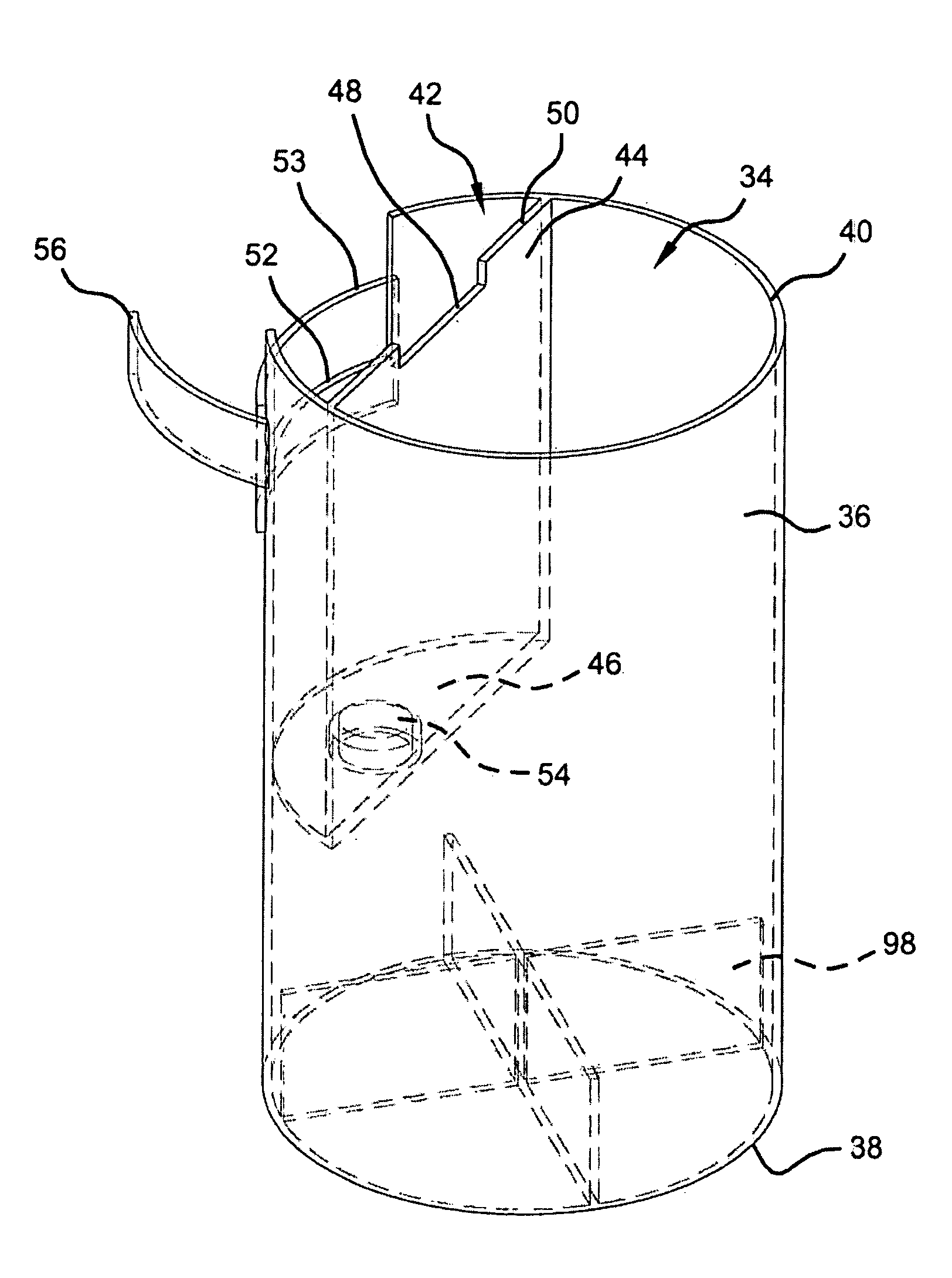
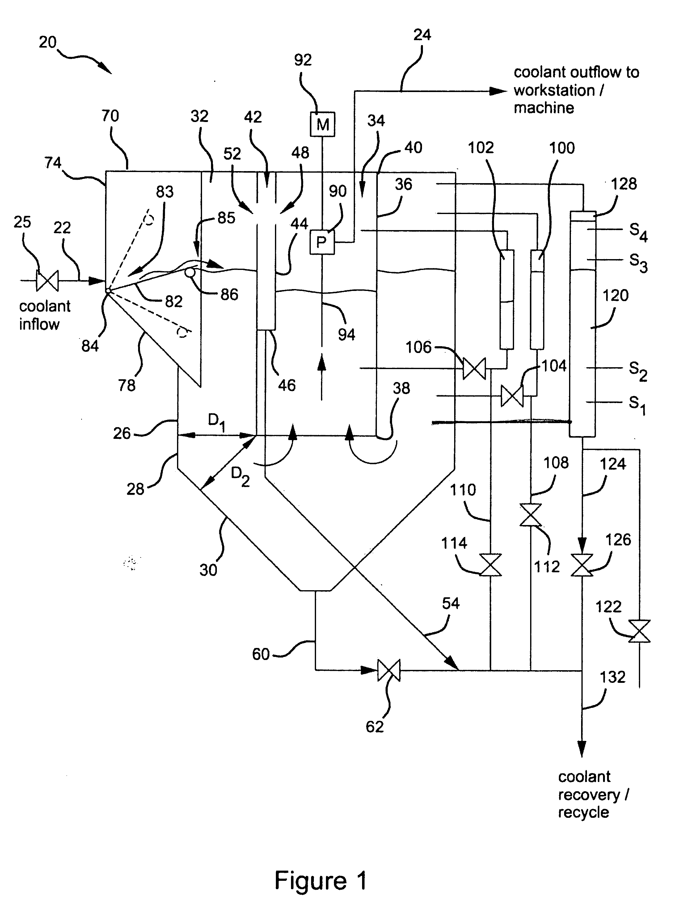
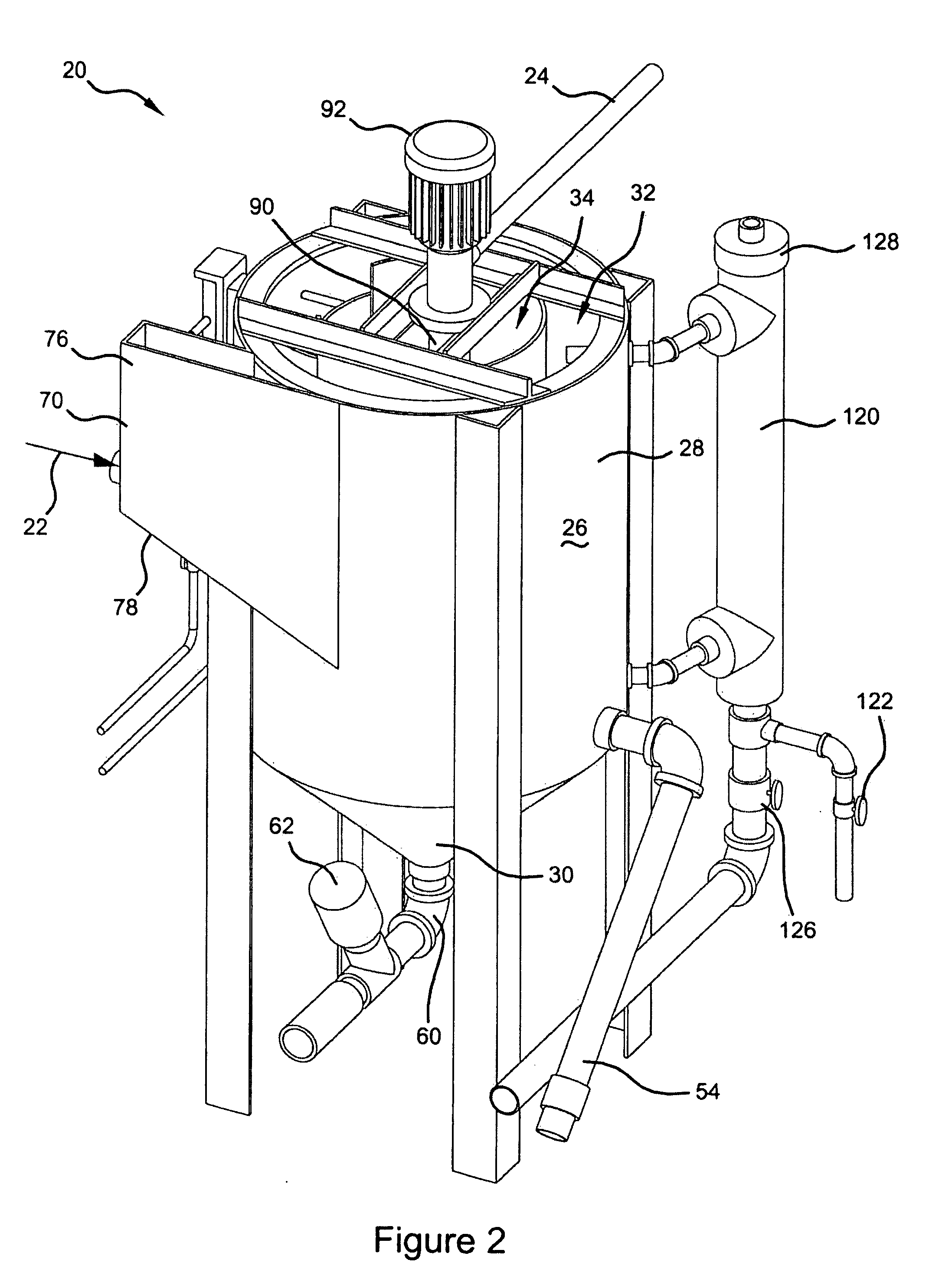
[0023] Referring to FIGS. 1-6, a fluid processing system 20 according to the present disclosure is shown. Fluid processing system 20 can be a coolant processing system and can receive a coolant inflow 22, remove particles and entrained air therefrom, and supply a coolant outflow 24 to a downstream workstation or machine. A valve 25 can control the flow of coolant into coolant processing system 20. Coolant processing system 20 can include a tank 26 having a peripheral side wall 28 and a bottom 30 that define an interior cavity 32. Hereinafter, fluid processing system 20 may be referred to as coolant processing system 20. It should be appreciated, however, that fluid processing system 20 can...


PUM


Abstract

A fluid processing system can include a tank having a peripheral side wall and a bottom defining an interior cavity. An inner chamber can be located within the interior cavity and spaced apart from the peripheral side wall. The inner chamber can have an open bottom in communication with the interior cavity through which fluid within the interior cavity flows thereby reducing the possibility for fluid with entrained air entering into the interior chamber. A flow path into the interior cavity can be tangential to the tank thereby inducing a cyclonic flow pattern around the inner chamber that can cause particles to migrate toward the peripheral wall and the bottom of the tank. The flow path can include a variable height weir that varies with the liquid level in the interior cavity thereby reducing the formation of entrained air in the fluid in the interior cavity.

Description

FIELD [0001] The present disclosure relates to fluid processing systems that remove particles and entrained air from the fluid flowing therethrough. BACKGROUND AND SUMMARY [0002] The statements in this section merely provide background and summary information related to the present disclosure and may not constitute prior art. [0003] Fluids, such as a coolant, can be used to cool, clean and / or lubricate a working tool / piece during a machining operation (e.g., turning, milling, grinding, boring, drilling, etc.). The fluid can be supplied by a pump at a desired pressure and / or flow rate. The used fluid is typically captured for recirculation / re-use. The used fluid can contain particles or debris as a result of a machining operation. The debris can damage the pump(s) used to supply the fluid to the working tool(s). Additionally, the fluid can contain entrained air or gas that can also be detrimental to the pump (e.g., cavitation) and other fluid handling devices used to transport the fl...

Claims


Application Information

Patent Timeline
Patent Type & Authority Applications(United States)
IPC IPC(8): F17D1/00
CPCB23Q11/1069Y10T137/86212
Inventor THOMPSON, DAVID
Owner THOMPSON DAVID
Why Eureka
Try Eureka