[0011]It is another object of the invention to provide an improved structure of a gas sensor which is designed to ensure the adhesion of an electric lead to a sensor element.
[0012]According to one aspect of the invention, there is provided an improved structure of a gas sensor which may be employed in measuring the concentration of a given component of exhaust emissions from automotive engines. The gas sensor has a length with a top end and a base end opposite the top end and comprises: (a) a sensor element responsive to a concentration of a given gas to output a
signal indicative thereof, the sensor element having a length with a top end and a base end opposite the top end; (b) a
porcelain insulator in which the sensor element is retained with the top end thereof oriented to the top end of the gas sensor and the base end thereof oriented to the base end of the gas sensor; and (c) a housing in which the porcelain insulator is retained. The sensor element includes an
oxygen ion-conductive
solid electrolyte layer with a first and a second surface opposed to each other, a measurement gas electrode which is formed on the first surface of the
ion-conductive solid electrolyte layer to be exposed to the gas and has a top end
lying on a side of the top end of the sensor element and a base end
lying on a side of the base end of the sensor element, a measurement gas electrode lead extending from the base end of the measurement gas electrode, a reference gas electrode formed on the second surface of the
ion-conductive solid electrolyte layer to be exposed to a reference gas, a dense protective layer covering the measurement gas electrode lead, and a porous protective layer disposed on the dense protective layer to cover the measurement gas electrode. The dense protective layer has a length with a top end
lying on the side of the top end of the sensor element and a base end lying on the side of the base end of the sensor element. The porous protective layer has a length with a top end lying on the side of the top end of the sensor element and a base end lying on the side of the base end of the sensor element. The base end of the dense protective layer protrudes from the base end of the porous protective layer by a distance of 5 mm or less. The base end of the porous protective layer lies inside the porcelain insulator. In other words, a sensing portion of the sensor element directly exposed to the gas is covered fully with the porous protective layer. The porous protective layer works to trap
foreign matter, e.g., residual matter, such as carbon, contained in exhaust emissions from the automotive
internal combustion engine, thereby minimizing the deposition of the
foreign matter on the measurement gas electrode and the measurement gas electrode lead which is one of factors causing the separation of the lead from the solid electrolyte layer.
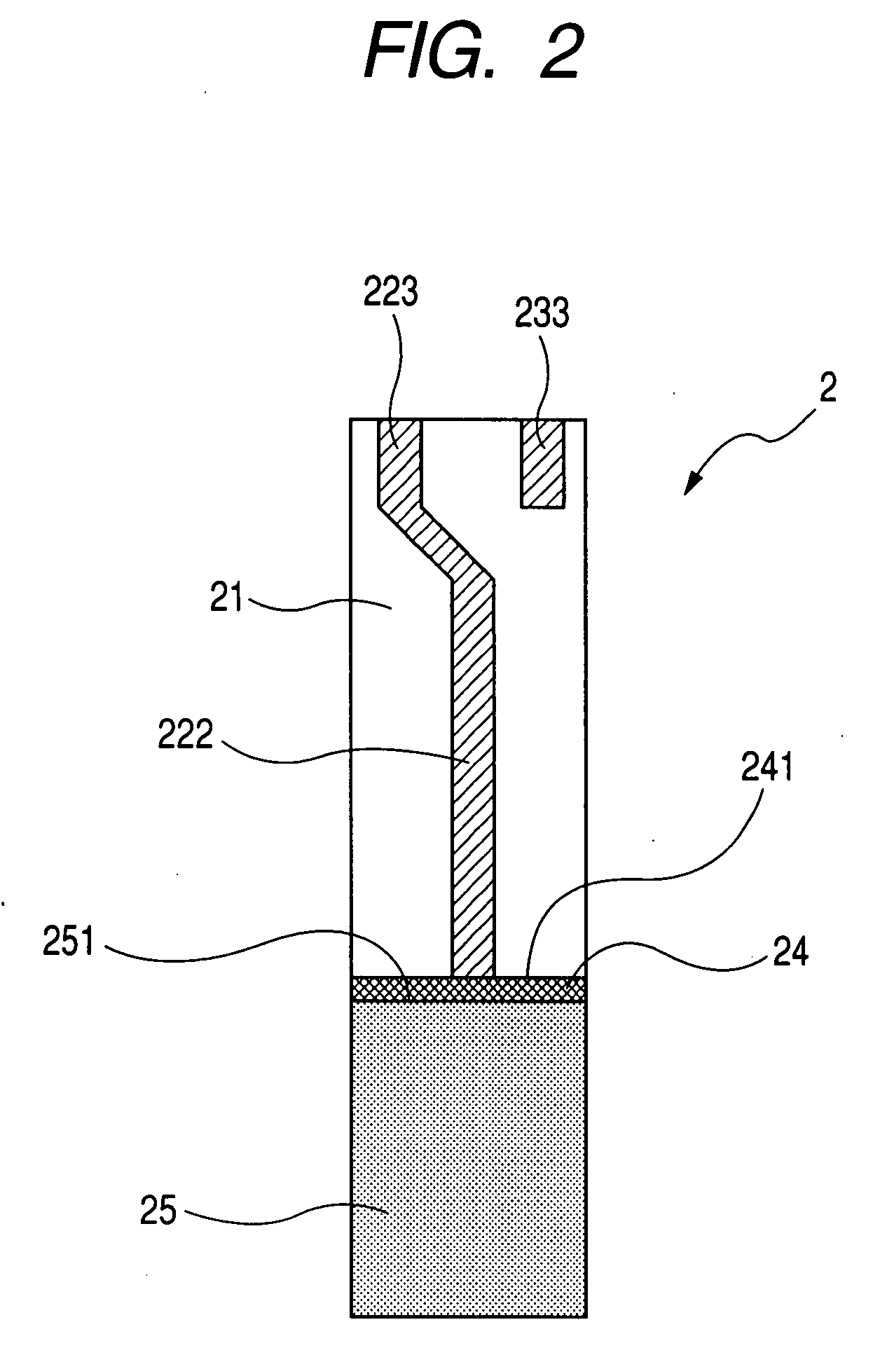
[0013]The protruding distance by which the dense protective layer protrudes from the base end of the porous protective layer 25 is 5 mm or less. This minimizes the separation of the measurement gas electrode lead arising from the entrance of water into the measurement gas electrode lead. For instance, in production processes of the gas sensor, the measurement gas electrode lead is exposed to water, so that it may enter the measurement gas electrode lead. When the
moisture in the measurement gas electrode lead is vaporized during heat treatment of the sensor element, it expands within the measurement gas electrode lead. If the measurement gas electrode lead is covered almost fully with the dense protective layer, the
water vapor will have nowhere to escape from the measurement gas electrode lead, which may result in breakage of the dense protective layer and separation or breakage of the measurement gas electrode lead. The porous protective layer covers most of the dense protective layer to enhance the
mechanical strength of the dense protective layer, thus causing the water vapor, as produced in the measurement gas electrode lead, to escape from a portion of the measurement gas electrode lead not covered with the dense protective layer. A portion of the dense protective layer not covered with the porous protective layer, however, may lack the mechanical strength required to withstand the pressure of water vapor, as produced in the measurement gas electrode lead. In order to minimize this affair, the sensor element of this embodiment is designed to set the protruding distance by which the dense protective layer protrudes from the base end of the porous protective layer to 5 mm or less to minimize the portion of the dense protective layer not covered with the porous protective layer. This minimizes the separation of the measurement gas electrode lead from the solid electrolyte layer.
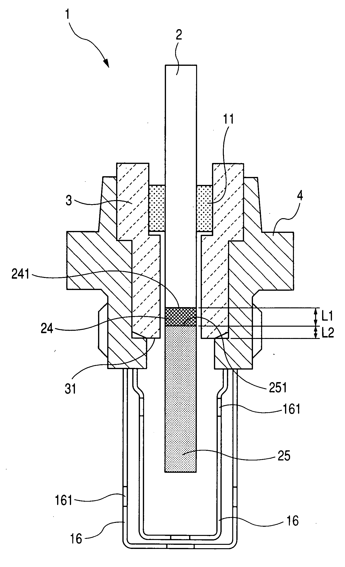
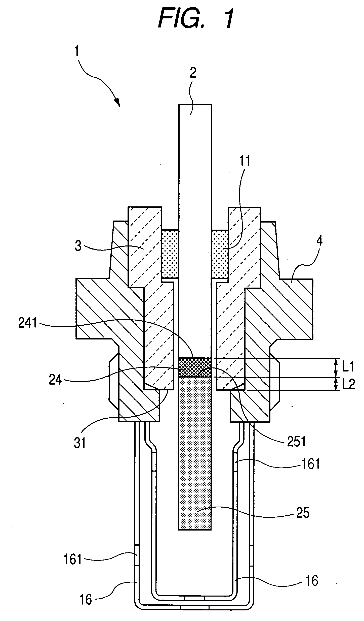
[0014]In the preferred mode of the invention, the gas sensor further comprises a sealing member and a second dense protective layer. The sealing member is disposed within the porcelain insulator to form a
hermetic seal between the sensor element and the porcelain insulator. The second dense protective layer is interposed between the sealing member and the sensor element, thereby minimizing the separation of the measurement gas electrode lead from the solid electrolyte layer.
[0016]According to another aspect of the invention, there is provided a gas sensor having a length with a top end and a base end opposite the top end which comprises: (a) a sensor element responsive to a concentration of a given gas to output a
signal indicative thereof, the sensor element having a length with a top end and a base end opposite the top end; (b) a porcelain insulator in which the sensor element is retained with the top end thereof oriented to the top end of the gas sensor and the base end thereof oriented to the base end of the gas sensor; and (c) a housing in which the porcelain insulator is retained. The sensor element includes an
oxygen ion-conductive solid electrolyte layer with a first and a second surface opposed to each other, a measurement gas electrode which is formed on the first surface of the ion-conductive solid electrolyte layer to be exposed to the gas and has a top end lying on a side of the top end of the sensor element and a base end lying on a side of the base end of the sensor element, a measurement gas electrode lead extending from the base end of the measurement gas electrode, a reference gas electrode formed on the second surface of the ion-conductive solid electrolyte layer to be exposed to a reference gas, a dense protective layer covering the measurement gas electrode lead, and a porous protective layer disposed on the dense protective layer to cover the measurement gas electrode. The dense protective layer has an opening through which the measurement gas electrode lead partially exposed, thereby permitting the water vapor, as developed in the measurement gas electrode lead when the sensor element is subjected to the heat treatment, to escape outside the dense protective layer, thus minimizing the breakage of the dense protective layer arising from the expansion of the
moisture to avoid the separation of the measurement gas electrode lead from the solid electrolyte layer.
[0017]In the preferred mode of the invention, the gas sensor may further include a sealing member disposed within the porcelain insulator to form a
hermetic seal between the sensor element and the porcelain insulator. The dense protective layer occupies an area of the sensor element placed in contact with the sealing member, thereby minimizing the separation of the measurement gas electrode lead from the solid electrolyte layer.

