

Solenoid and pump using the same
a solenoid and pump technology, applied in the direction of piston pumps, positive displacement liquid engines, magnetism bodies, etc., can solve the problems of inability to increase permeance, wide thrust generation range cannot be always gained, and high thrust cannot be highly increased, so as to achieve the effect of high thrust and improved pumping ability
- Summary
- Abstract
- Description
- Claims
- Application Information
AI Technical Summary
Benefits of technology
Problems solved by technology
Method used
Image

Examples
first embodiment
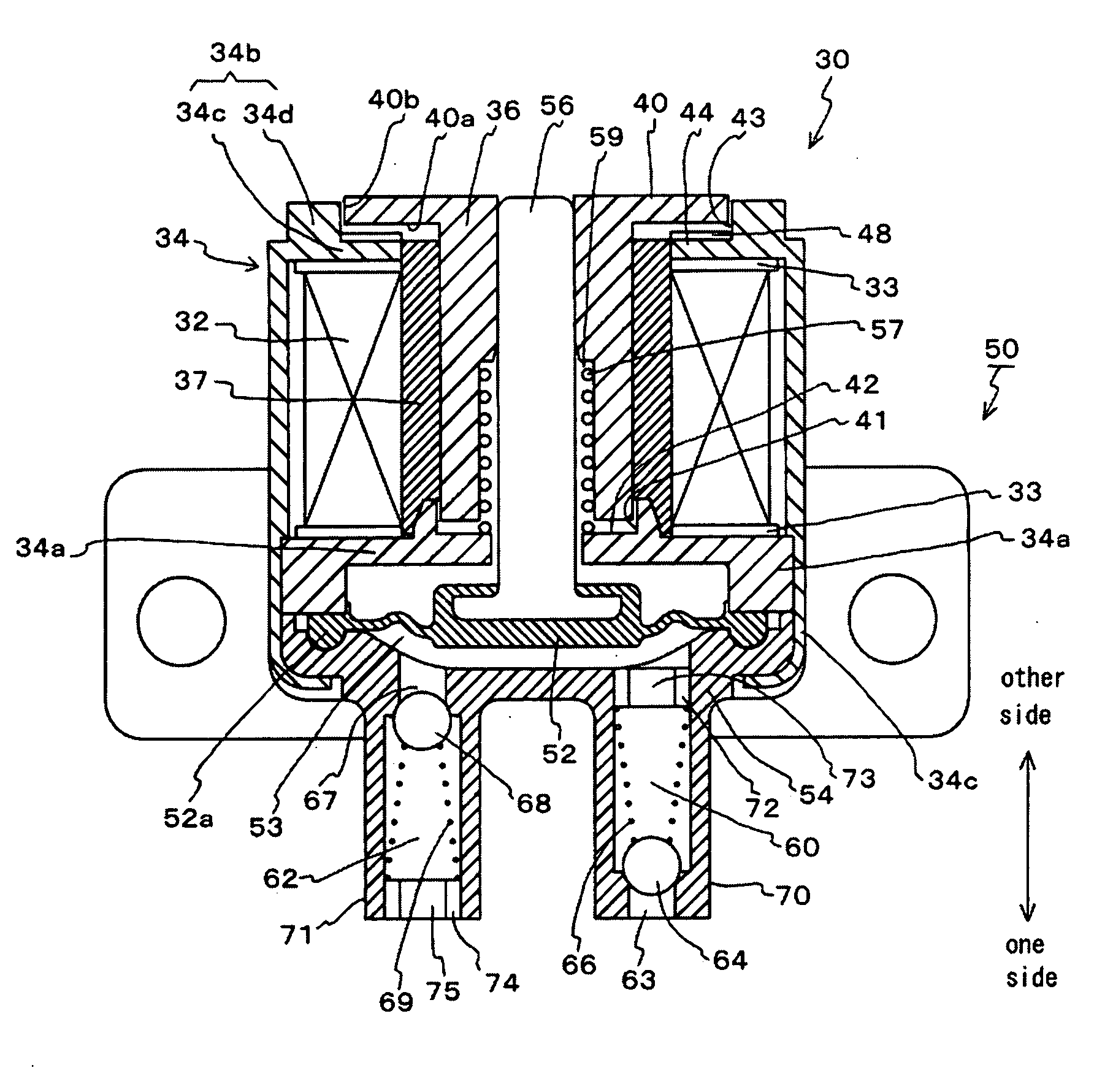
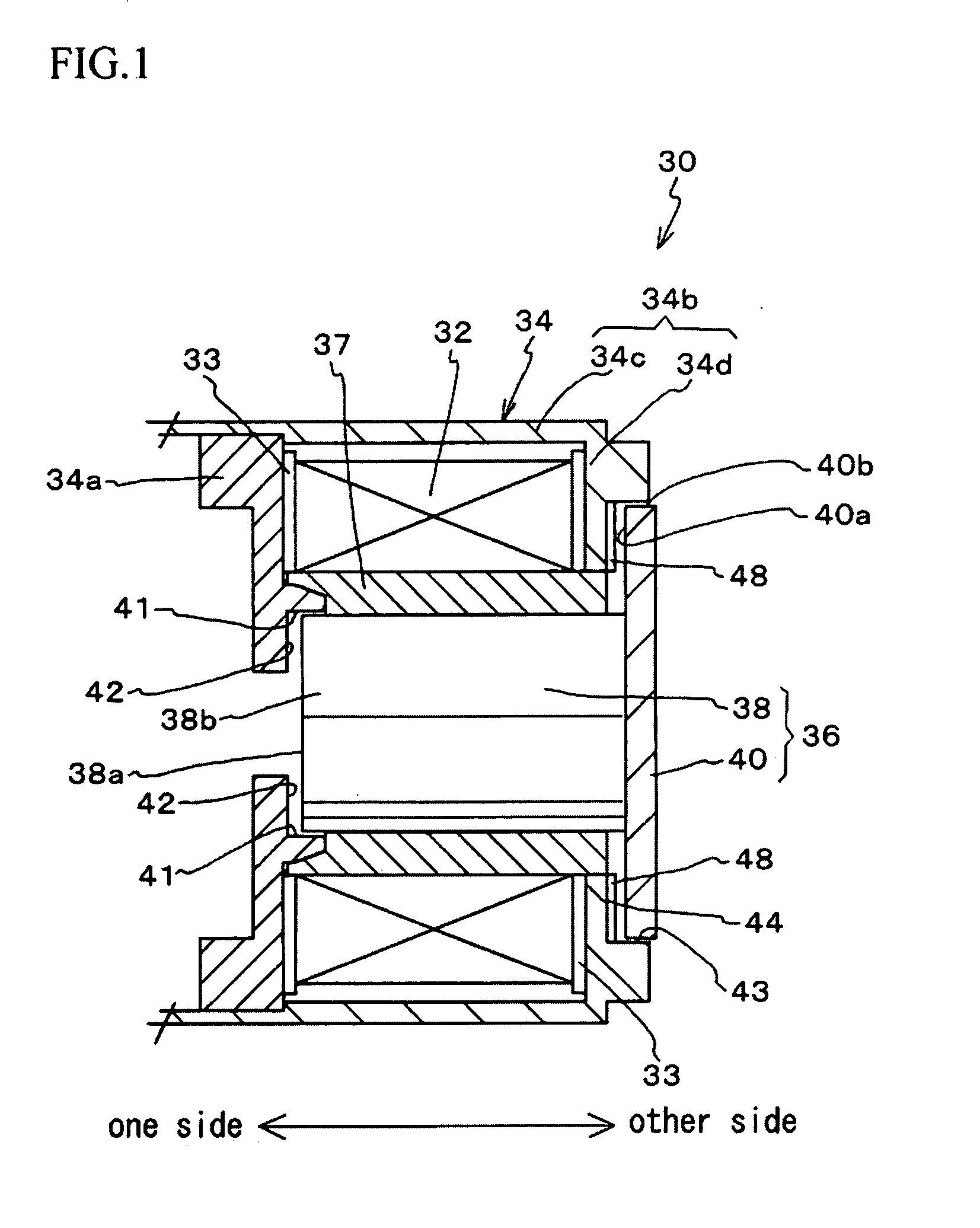
[0044]A solenoid of a first embodiment of the present invention will be explained with reference to FIG. 1.
[0045]A solenoid 30 has an excitation coil 32, a yoke 34 and a movable element 36. The movable element 36 is accommodated in a guide pipe 37. The guide pipe 37 is made of a nonmagnetic material, e.g., synthetic resin.
[0046]The yoke 34 is made of a magnetic material and encases the excitation coil 32. Insulating members 33 are provided between both ends of the excitation coil 32 and the yoke 34.
[0047]The yoke 34 comprises an upper yoke part 34a, which is provided on one side (on the left side in the FIG. 1 to FIG. 4) of the excitation coil 32, and a lower yoke part 34b, which is provided on the other side (on the right side in the FIG. 1 to FIG. 4) thereof.
[0048]Note that, the upper yoke part 34a acts as the first yoke part of the claims; the lower yoke part 34b acts as the second yoke part thereof. In the present embodiment, the lower yoke part 34b covers a side face of the exc...
second embodiment
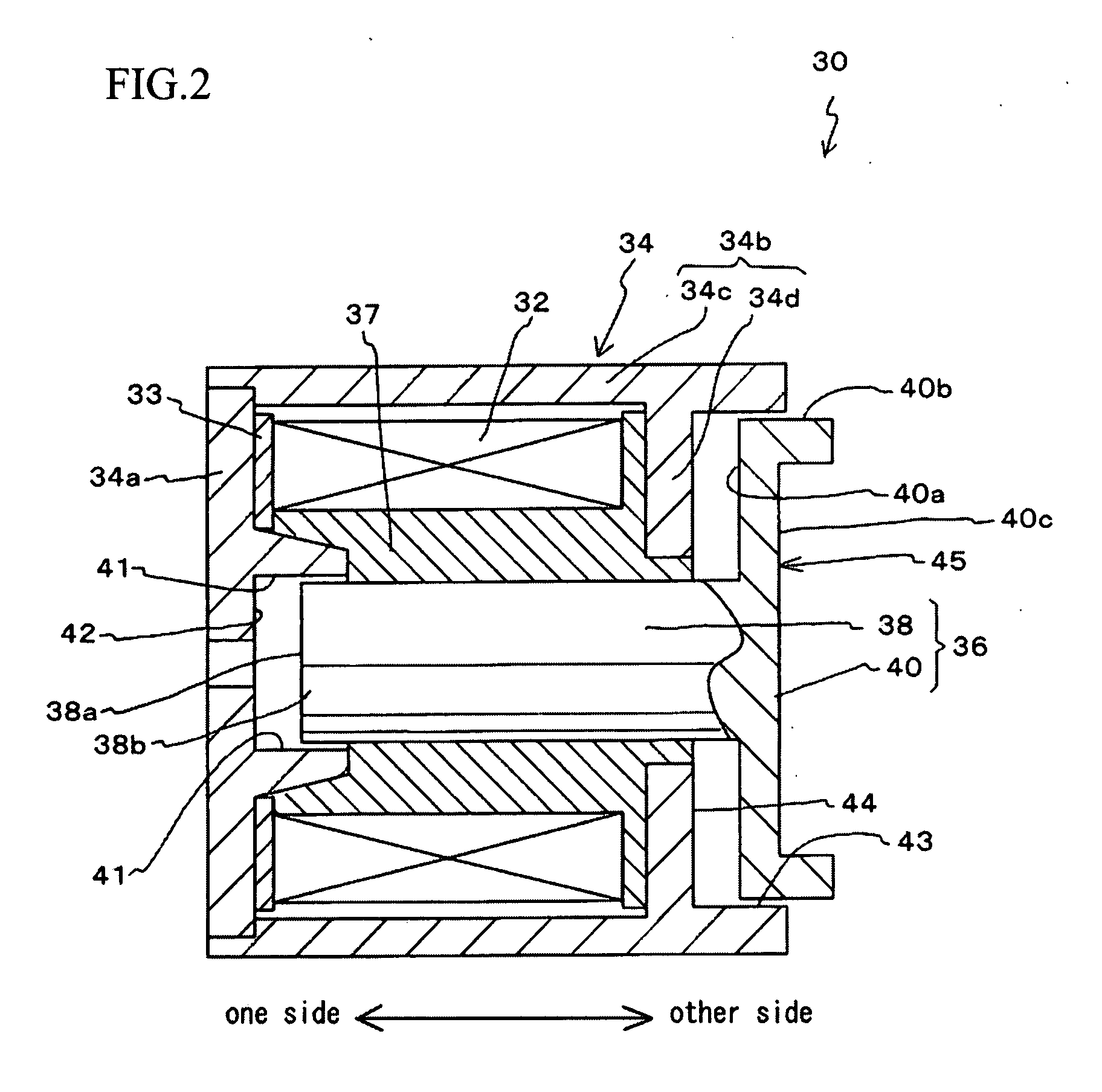
[0061]Next, the solenoid of a second embodiment will be explained with reference to FIGS. 2-4.
[0062]Note that, structural elements explained in the first embodiment are assigned the same symbols and explanation will be omitted.
[0063]In the present embodiment, a concave section 45 is formed in the end face 40c of the large diameter section 40 of the movable element 36 located on the other side and is caved toward the one side. By forming the concave section 45 in the end face 40c of the large diameter section 40 located on the other side, weight of the movable element 36 can be reduced without reducing a facing area of the outer circumferential face 40b of the large diameter section 40 with respect to the lower yoke part 34b.
[0064]By insert-molding or outsert-molding the guide pipe 37 with the upper yoke part 34a or the lower yoke part 34b, the upper yoke part 34a or the lower yoke part 34b can be suitably assembled thereto.
[0065]In an insert-molding process, the upper yoke part 34a...
experimental example
(Experimental Example)
[0073]The solenoid having the structure shown in FIG. 1 was produced as an experimental example. Thrust characteristics of the experimental example and a conventional solenoid, which has the large diameter section 40 and no surface facing the outer circumferential face 40b of the large diameter section 40, were measured. The results are shown in a graph of FIG. 5.
[0074]A horizontal axis of the graph indicates a projection length of the movable element moving toward the other side; a vertical axis thereof indicates thrust.
[0075]According to the graph, unlike the conventional solenoid, the solenoid of the experimental example was capable of generating great thrust within an entire stroke except when the movable element 36 is at a position closest to the one side.
[0076]Therefore, the thrust can be increased by forming the third facing surface 43, which faces the outer circumferential face 40b of the large diameter section 40, in the lower yoke part 34b.
(Embodimen...
PUM
| Property | Measurement | Unit |
|---|---|---|
| diameter | aaaaa | aaaaa |
| cylindrical shape | aaaaa | aaaaa |
| diameter | aaaaa | aaaaa |
Abstract
Description
Claims
Application Information