Voltage controlled oscillator circuit

a voltage control and oscillator technology, applied in the direction of pulse generator, pulse manipulation, pulse technique, etc., can solve the problems of phase noise increase, phase noise deterioration, and current in the voltage to current converter circuit is also decreased, so as to prevent a deterioration of phase noise characteristics and expand the frequency range

Inactive Publication Date: 2007-10-11
FUJITSU LTD
View PDF6 Cites 6 Cited by
  • Summary
  • Abstract
  • Description
  • Claims
  • Application Information

AI Technical Summary

Benefits of technology

[0025]An object of the present invention is to provide a voltage controlled oscillator circuit that is not disadvantageous in power consumption and an occupied area and is capable of enlarging a frequency range without a deterioration of the phase noise characteristics even in a low frequency range.
[0031]According to the present invention, it is possible to enlarge a frequency range while preventing a deterioration of phase noise characteristics in a low frequency range without a disadvantage in power consumption and an occupied area.

Problems solved by technology

For this reason, there is a problem of deterioration of the phase noise characteristics.
In other words, the phase noise increases if current in the voltage to current converter circuit is decreased.
As a result, current in the voltage to current converter circuit is also decreased so that the phase noise increases.
In the case of the second method, there is a problem of large current consumption.
Although it is expected inherently that the power consumption becomes smaller in a low frequency than in a high frequency, the power consumption becomes large in the second method since the VCO always operates at a high frequency.
In the case of the third method, there is a problem of large power consumption and a large area occupied by circuit elements since a plurality of VCOs exist.
In the case of the method disclosed in the second document (Japanese unexamined patent publication No. 7-58602), there is a problem of a complicated circuit and a large area occupied by circuit elements since each delay circuit needs transistors for the current mirror circuit.

Method used


Image

  • Voltage controlled oscillator circuit
  • Voltage controlled oscillator circuit
  • Voltage controlled oscillator circuit

Examples


first embodiment

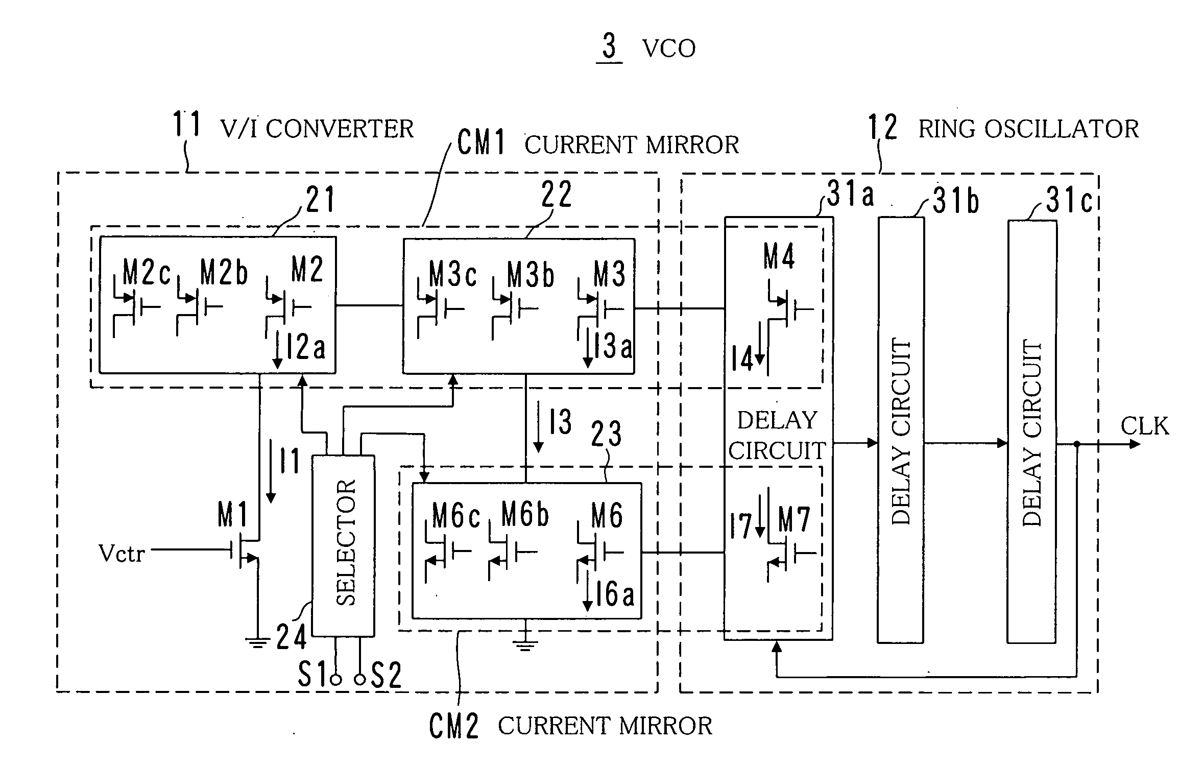
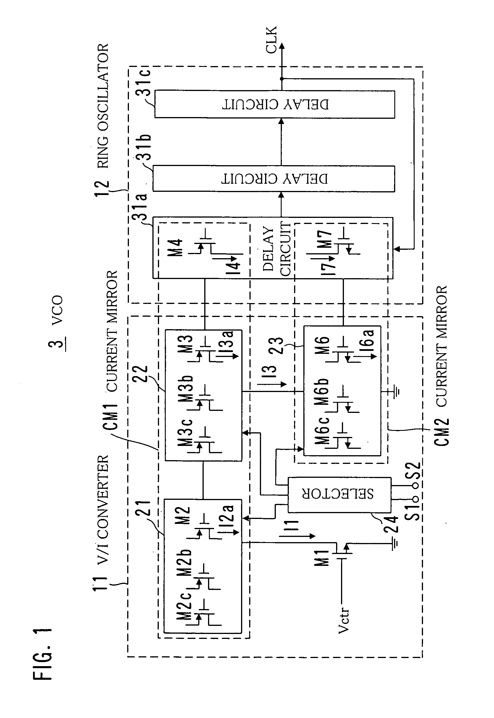
[0045]FIG. 1 is a circuit diagram of a VCO 3 according to a first embodiment of the present invention.

[0046]As shown in FIG. 1, the VCO 3 is made up of a voltage to current converter circuit 11 and a ring oscillator 12.

[0047]The voltage to current converter circuit 11 converts input voltage (control voltage) Vctr that is supplied to the VCO 3 into current I1, and current that flows in the ring oscillator 12 is controlled in accordance with the generated current I1 so that an oscillation frequency is altered.

[0048]The ring oscillator 12 is made up of a plurality of delay circuits 31a, 31b and 31c that are connected like a ring. Although three delay circuits 31 are used in this embodiment, it is possible to use five, seven or other number of delay circuits. An oscillation frequency of the ring oscillator 12 alters in accordance with current flowing in each delay circuit 31. For example, as the current increases, the oscillation frequency is raised because a capacitance existing in the...

second embodiment

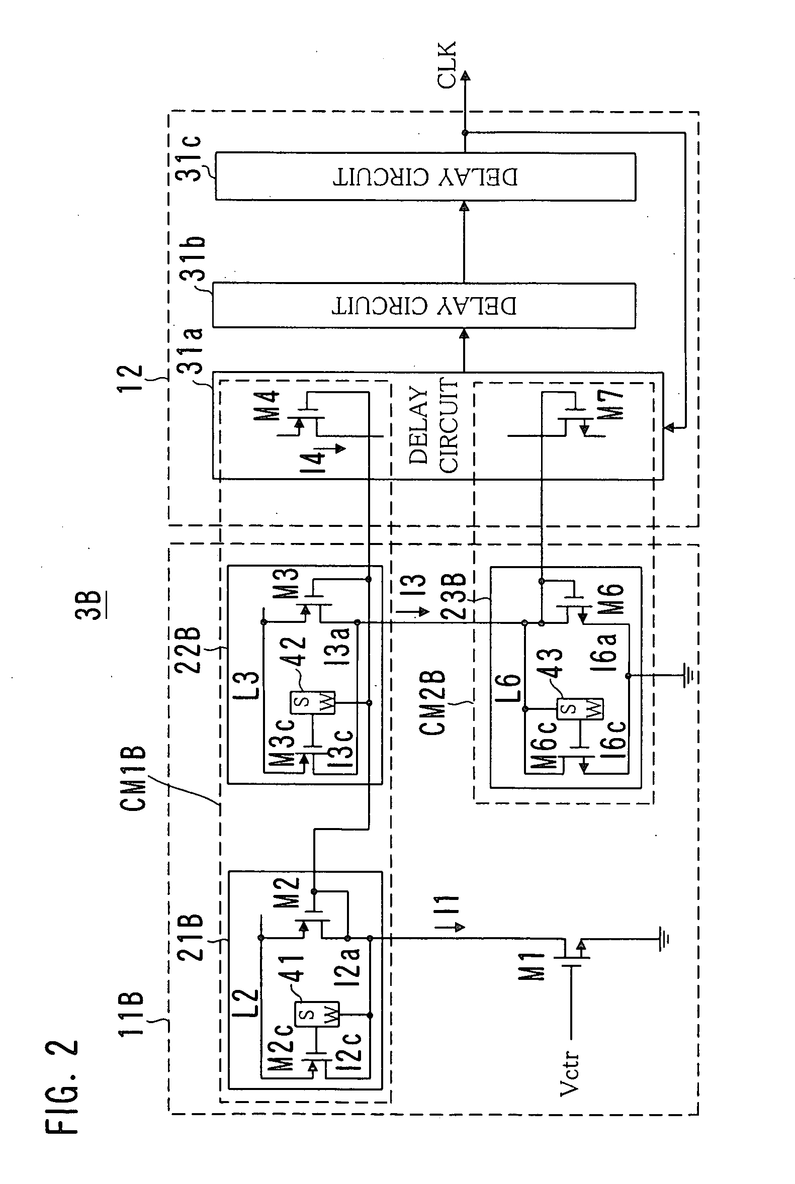
[0078]FIG. 2 is a circuit diagram of a VCO 3B according to a second embodiment of the present invention.

[0079]The VCO 3B shown in FIG. 2 is provided with switching circuits 41-43 for turning on and off the transistors M2b, M2c, M3b, M3c, M6b and M6c that can be connected in parallel, and they are disposed between gates and drains of the transistors, respectively. Note that lines L2 and L3 are power source lines.

[0080]In FIG. 2, circuits for the transistors M2b, M3b and M6b and the selector 24 are omitted. It is the same in the following drawings.

[0081]When the switching circuits 41-43 are selectively turned on or off by the selector 24, the gate and the drain are selectively connected to each other or separated from each other, respectively. Thus, any one of the transistors M2b, M2c, M3b, M3c, M6b and M6c is connected in parallel with the transistors M2, M3 and M6, respectively.

third embodiment

[0082]FIG. 3 is a circuit diagram of a VCO 3C according to a third embodiment of the present invention.

[0083]The VCO 3C shown in FIG. 3 is provided with switching circuits 44-46 for turning on and off the transistors M2b, M2c, M3b, M3c, M6b and M6c that can be connected in parallel, and they are disposed between sources of the transistors and the lines L3, L4 and L6, respectively.

[0084]When the switching circuits 44-46 are selectively turned on or off by the selector 24, the gates and lines L3, L4 and L6 are selectively connected to each other or separated from each other, respectively. Thus, any one of the transistors M2b, M2c, M3b, M3c, M6b and M6c is connected in parallel with the transistors M2, M3 and M6, respectively.


PUM


Abstract

A voltage controlled oscillator circuit includes a ring oscillator including a plurality of delay circuits that are connected like a ring and a voltage to current converter circuit for controlling current flowing in the ring oscillator so as to change an oscillation frequency thereof. The voltage to current converter circuit 11 is provided with a shunt circuit for shunting a part of current obtained by converting input voltage, and the shunted part of the current is used for controlling the current flowing in the ring oscillator.

Description

BACKGROUND OF THE INVENTION[0001]1. Field of the Invention[0002]The present invention relates to a voltage controlled oscillator circuit that is used for a phase locked loop circuit or the like. In particular, the present invention relates to a voltage controlled oscillator circuit that is capable of outputting a wide frequency range.[0003]2. Description of the Prior Art[0004]Conventionally, voltage controlled oscillator (VCO) circuits are used for generating a carrier or a clock signal or as an element constituting a phase locked loop (PLL) circuit in various communication devices such as a mobile telephone, computer-related devices and other various digital devices or control devices (see Japanese unexamined patent publication No. 2002-171165).[0005]As shown in FIG. 11, a VCO 80 is basically made up of a ring oscillator 82 including a plurality of delay circuits 81a, 81b, . . . , 81n connected like a ring and a voltage to current converter circuit 83 for controlling current that f...

Claims


Application Information

Patent Timeline
Patent Type & Authority Applications(United States)
IPC IPC(8): H03K3/03
CPCH03K2005/00032H03K3/0315
Inventor YAMAGUCHI, TATSUYAHAYAMI, KAZUNORIYAMAMOTO, SATOSHI
Owner FUJITSU LTD
Why Eureka
Try Eureka