Image processing apparatus

a technology of image processing and apparatus, applied in the direction of digital output to print units, electrographic processes, instruments, etc., can solve the problems of inability of the control unit of the image processing apparatus to perform normal control processing, delay in execution of a new processing request, and suspension of processing in progress, so as to achieve the effect of suppressing the power consumption of the apparatus

Active Publication Date: 2007-10-11
SHARP KK
View PDF11 Cites 70 Cited by
  • Summary
  • Abstract
  • Description
  • Claims
  • Application Information

AI Technical Summary

Benefits of technology

[0014]The object of the present invention is to provide an image processing apparatus that can update the control information kept in a controlling unit of the apparatus suppressing the power consumption in the apparatus as much as possible without suspending the processing in progress or delaying the execution of the request for new processing.

Problems solved by technology

Usually, a controlling unit of an image processing apparatus is incapable of performing normal control processing while updating control information (programs and control parameters) kept in the controlling unit.
This leads to such a trouble that processing in progress is suspended or execution of a new processing request is delayed due to updating the control information when updating of the control information is carried out in a situation where an image processing is in progress or a request for execution of the image processing seems to be raised with high possibility.
If the image processing apparatus carries out a control information updating processing in a time zone during which the image processing apparatus rarely works (at night, on holiday, etc.), the controlling unit must be kept in energized state until such time zone and therefore, there is a problem that the electric power is consumed wastefully.

Method used


Image

  • Image processing apparatus
  • Image processing apparatus
  • Image processing apparatus

Examples


Embodiment Construction

[0055]Embodiments of the present invention will now be described with reference to the accompanying drawings to facilitate understanding of the present invention. The following embodiments provide examples embodying the present invention, and should not be construed as a limitation to the technical scope of the present invention.

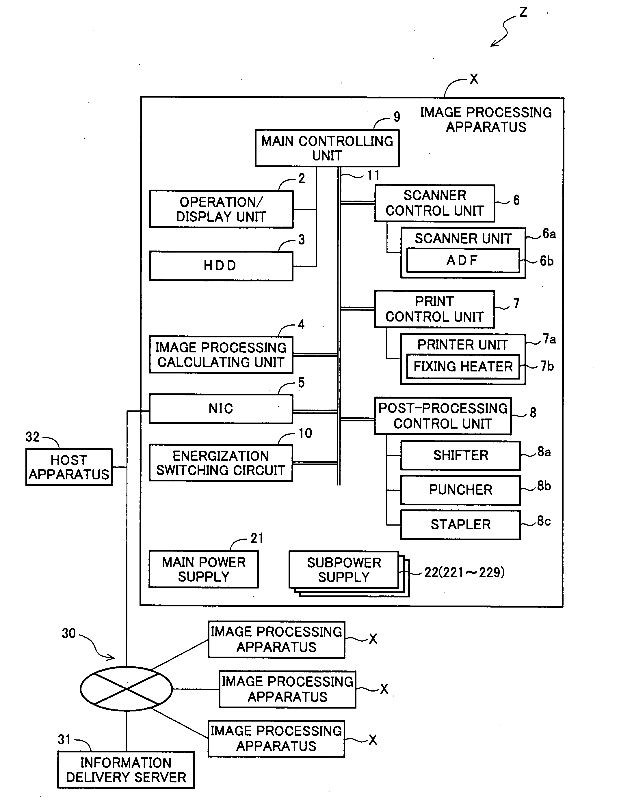
[0056]FIG. 1 is a block diagram showing the general structure of the image processing apparatus X according to the embodiment of the present invention and of the network system Z including the image processing apparatus X as a constituent element. The network system Z includes one or more image processing apparatuses X, and an information delivery server 31 that can communicate with each image processing apparatus X via a network 30, such as LAN and the Internet.

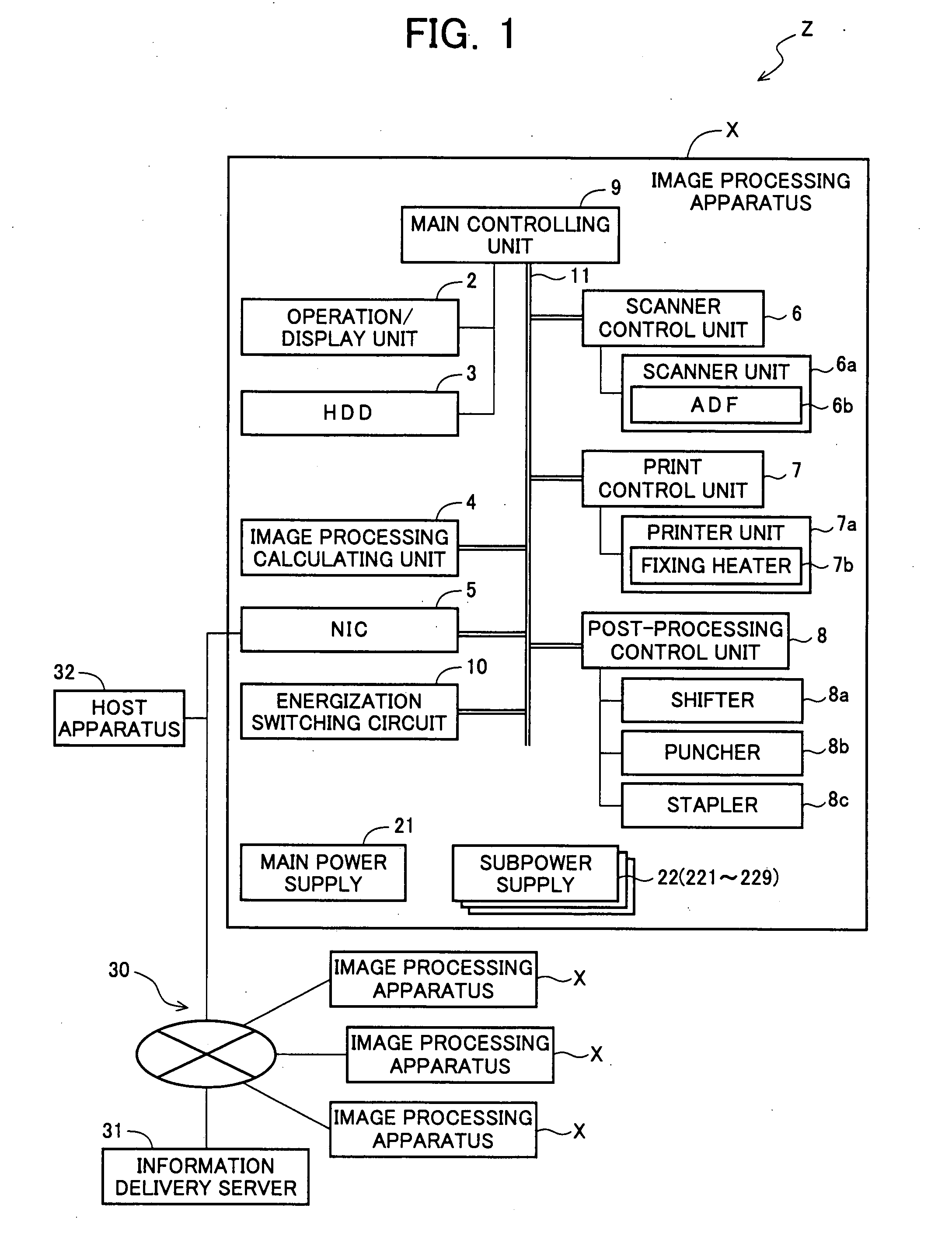
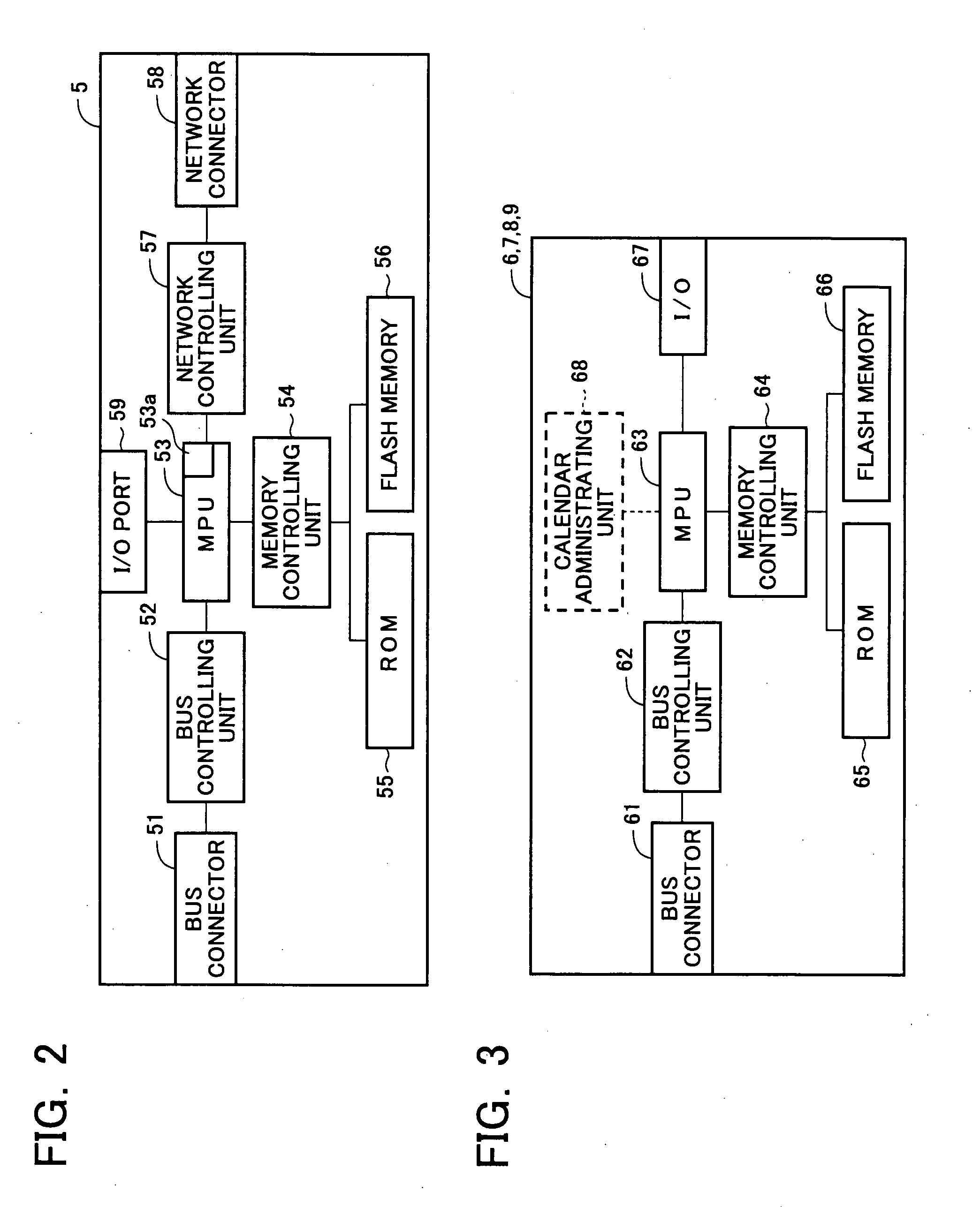
[0057]The image processing apparatus X includes one or more controlling units 6 to 9 each of which has a memory unit keeping firmware used for controlling (program for executing various control proce...


PUM


Abstract

An image processing apparatus executes the processing of updating control information kept in the controlling units included in it without suspending an on-going processing and delaying the execution of a new processing request with less power consumption. When the controlling units are in a sleep mode or in non-energized state, NIC determines whether or not updating of firmware kept in each controlling unit is necessary by communicating with the information delivery server. The NIC controls an energization switching circuit to start up exclusively the controlling unit keeping the firmware determined necessary to be updated and replaces the firmware kept in the started controlling unit with the latest version of firmware obtained from the information delivery server.

Description

CROSS-NOTING PARAGRAPH[0001]This Non-provisional application claims priority under 35 U.S.C. §119 (a) on Patent Application No. 2006-104485 filed in JAPAN on Apr. 5, 2006, the entire contents of which are hereby incorporated herein by reference.FIELD OF THE INVENTION[0002]The present invention relates to an image processing apparatus which includes a communication unit that communicates with an external device, and a controlling unit that controls devices based on a given control information.BACKGROUND OF THE INVENTION[0003]An image processing apparatus, such as a multi-function machine including a printer, scanner, facsimile machine, and copier or functions thereof, generally includes a communicating unit (such as a NIC (Network Interface Card) or a modem (Modulator-Demodulator)) that communicates with an external apparatus (such as a computer or other image processing apparatuses) through a communication medium such as a network or telephone lines. Some of such image processing ap...

Claims


Application Information

Patent Timeline
Patent Type & Authority Applications(United States)
IPC IPC(8): G06K15/00
CPCG03G15/5004G03G2215/00109G06F8/67H04N1/00H04N1/00244H04N1/00885G03G15/5083H04N1/00904H04N1/0097H04N1/00973H04N1/32593H04N2201/0094Y02B60/183H04N1/00896G06F8/656Y02D10/00
Inventor OKAMOTO, YUJI
Owner SHARP KK
Why Eureka
Try Eureka