Cooling channel for a fan motor for a ventilation, heating, and/or air conditioning system

a cooling channel and fan motor technology, applied in combination devices, dispersed particle filtration, using liquid separation agents, etc., can solve problems such as damp air flow in the electric motor, serious damage to the motor, and exposure to damp air flow

Active Publication Date: 2007-10-11
VALEO SYST THERMIQUES
View PDF7 Cites 17 Cited by
  • Summary
  • Abstract
  • Description
  • Claims
  • Application Information

AI Technical Summary

Problems solved by technology

However, this method of cooling the electric motor has one great drawback in that the diverted air flow may be damp.
The electric motor may therefore come into contact with water, exposing it to a serious risk of damage.
The problem is therefore how to reduce the amount of water transported by the air flow through the secondary channel and thus avoid having the electric motor coming into contact with a liquid or with over-humid air when it is running.

Method used


Image

  • Cooling channel for a fan motor for a ventilation, heating, and/or air conditioning system
  • Cooling channel for a fan motor for a ventilation, heating, and/or air conditioning system
  • Cooling channel for a fan motor for a ventilation, heating, and/or air conditioning system

Examples


Embodiment Construction

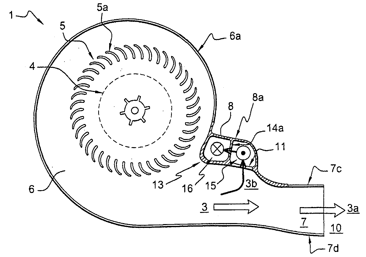
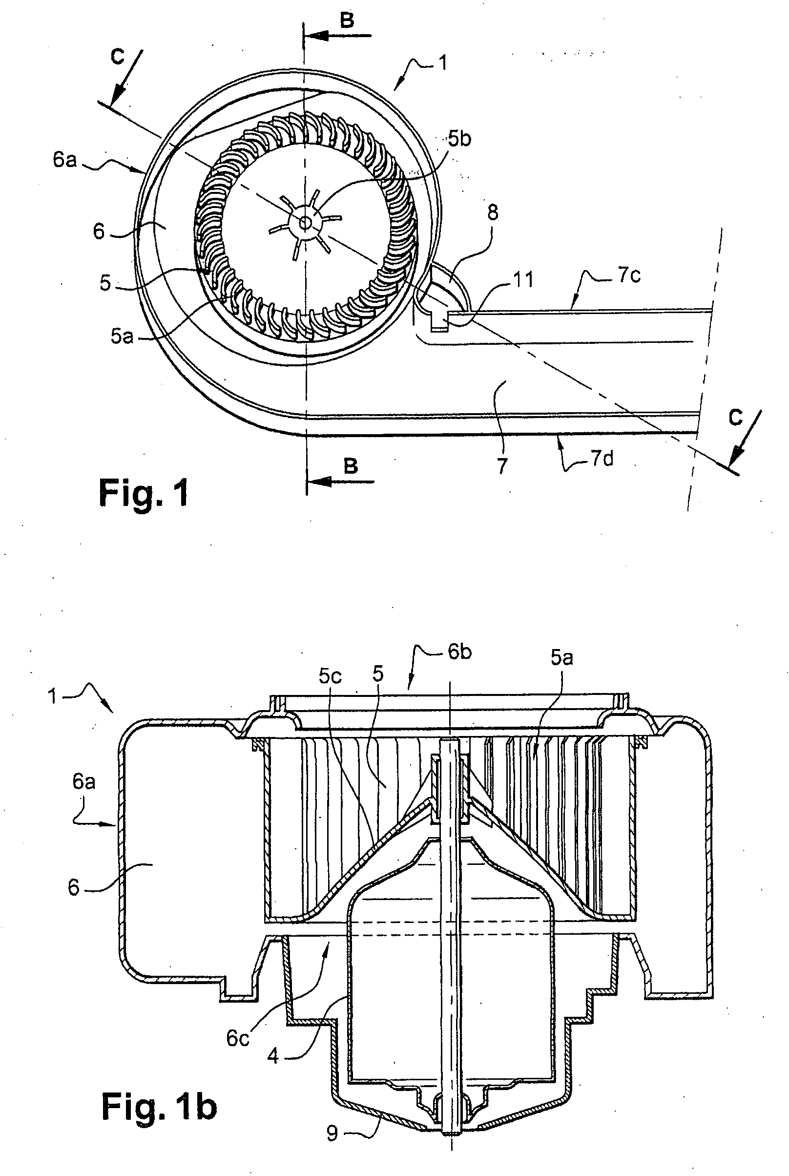
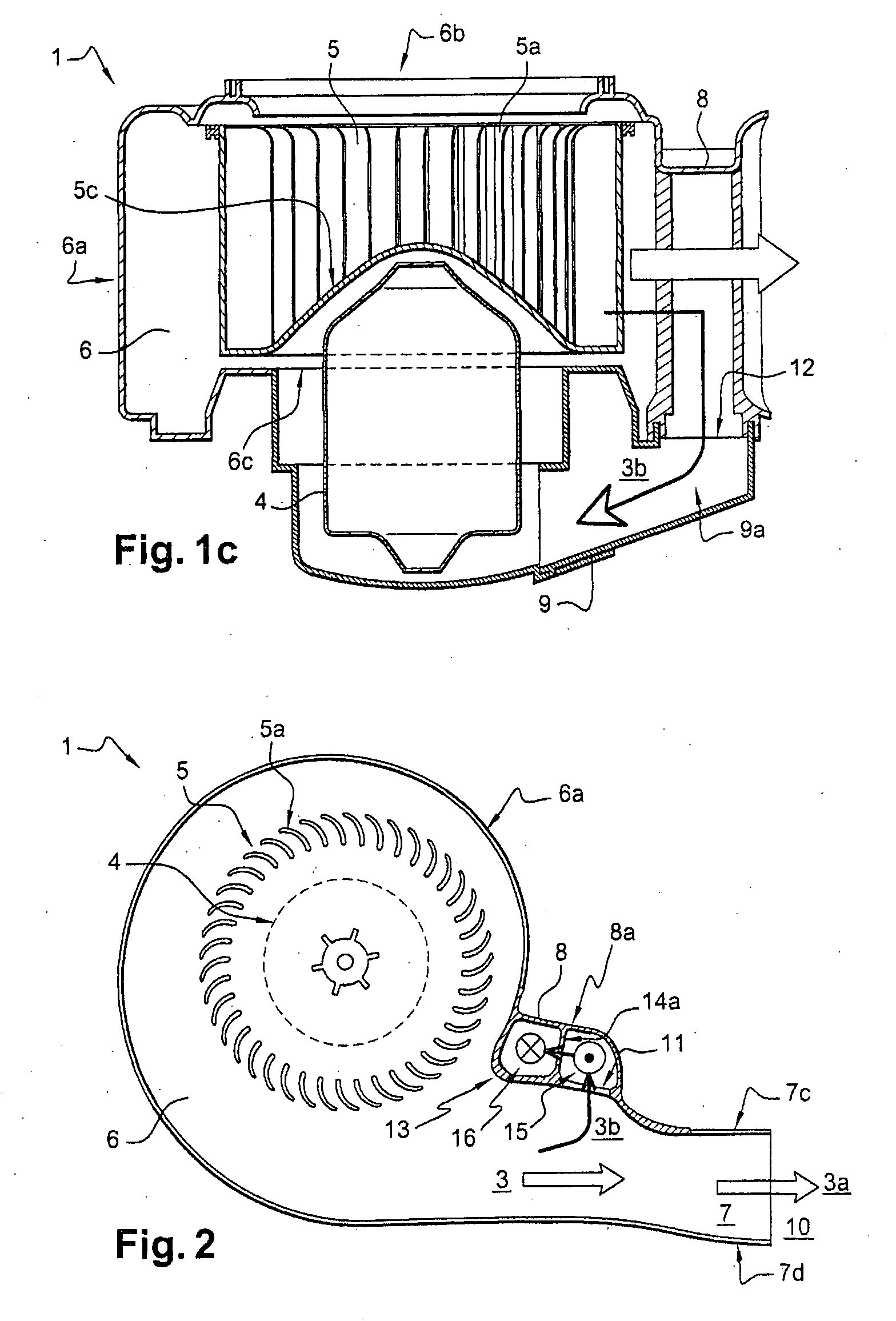
[0030]Parts that are common both to the prior art illustrated in FIGS. 1-1c and to the invention to which this application relates are given the same references.

[0031]FIGS. 2-7 show a ventilation device 1, itself designed to be incorporated into a ventilation / heating, ventilation / heating / air conditioning or ventilation / air conditioning appliance for a motor vehicle. FIG. 8 illustrates a ventilation / heating / air conditioning system 100 comprising the ventilation device 1 consisting of a casing 6 in the form of a volute, a blower impeller 5, and channels (7, 8, 15 and 16). The system 100 also comprises an evaporator 200 and a radiator 300 (both located in the main channel 7), distribution flaps 400, and air outlets 500 to the cabin.

[0032]A ventilation device 1 is shown in FIGS. 2 and 3. This ventilation device 1 comprises: a volute-shaped casing 6, that is, a casing defining a circular air channel whose cross section increases between a volute tongue and an air outlet; an electric moto...


PUM

PropertyMeasurementUnit
heightaaaaaaaaaa
total heightaaaaaaaaaa
volumeaaaaaaaaaa

Abstract

Ventilating device (1) comprising a casing (6) intended to channel at least one air flow (3) created by a blower wheel (5), the said casing (6) delimites a main air channel (7) in which a main air flow (3a) circulates and a secondary air channel (8) intended to bring towards a motor (4) a secondary air flow (3b) in order to cool the motor (4), the said secondary air channel (8) comprising a inlet (11) arranged in a main channel wall (7c) and a outlet arranged in a plan containing a casing end by which the wheel (5) is introduced, the said secondary channel (8) further comprising a means intended to change at least twice the direction of the secondary air flow (3b) when the secondary air flow (3b) passes through the secondary air channel (8).

Description

TECHNICAL FIELD OF THE INVENTION [0001]The present invention relates to a ventilation device that creates an air flow for supplying an air conditioning and / or heating system. The present invention makes it possible to cool an electric motor by means of an air flow. The present invention relates more particularly to a ventilation device for a motor vehicle.BACKGROUND OF THE INVENTION [0002]To ventilate, and to deliver hot or cold air into, the cabin of a motor vehicle, a ventilation device is connected to an air conditioning and / or heating system to supply air to the motor vehicle cabin. As illustrated in FIGS. 1, 1b, and 1c, the ventilation device 1 comprises a casing 6, an electric motor 4, and a blower impeller 5, the latter having vanes 5a and a hub 5b and being driven by this motor. The casing 6, which is usually shaped like a spiral cylinder, comprises a peripheral wall 6a and two open ends 6b, 6c, the first open end 6b acting as the air inlet of the ventilation device 1 and th...

Claims


Application Information

Patent Timeline
Patent Type & Authority Applications(United States)
IPC IPC(8): F01B25/00F04D29/44B01D45/00
CPCF04D29/584F04D25/082F04D29/706F04D29/5806
Inventor POUYSEGUR, SERGE
Owner VALEO SYST THERMIQUES
Why Eureka
Try Eureka