Mechanical coupling for a rotor shaft assembly of dissimilar materials

Inactive Publication Date: 2007-10-11
HAMILTON SUNDSTRAND CORP
View PDF13 Cites 27 Cited by
  • Summary
  • Abstract
  • Description
  • Claims
  • Application Information

AI Technical Summary

Benefits of technology

[0012] The present invention therefore provide an uncomplicated mechanical coupling for coupling a ce

Problems solved by technology

However, higher turbine inlet temperature requires temperature and oxidation resistant materials such as ceramics.
The difference in thermal expansion results in thermal stress that may lessen the connection between the ceramic rotor

Method used


Image

  • Mechanical coupling for a rotor shaft assembly of dissimilar materials
  • Mechanical coupling for a rotor shaft assembly of dissimilar materials
  • Mechanical coupling for a rotor shaft assembly of dissimilar materials

Examples


Embodiment Construction

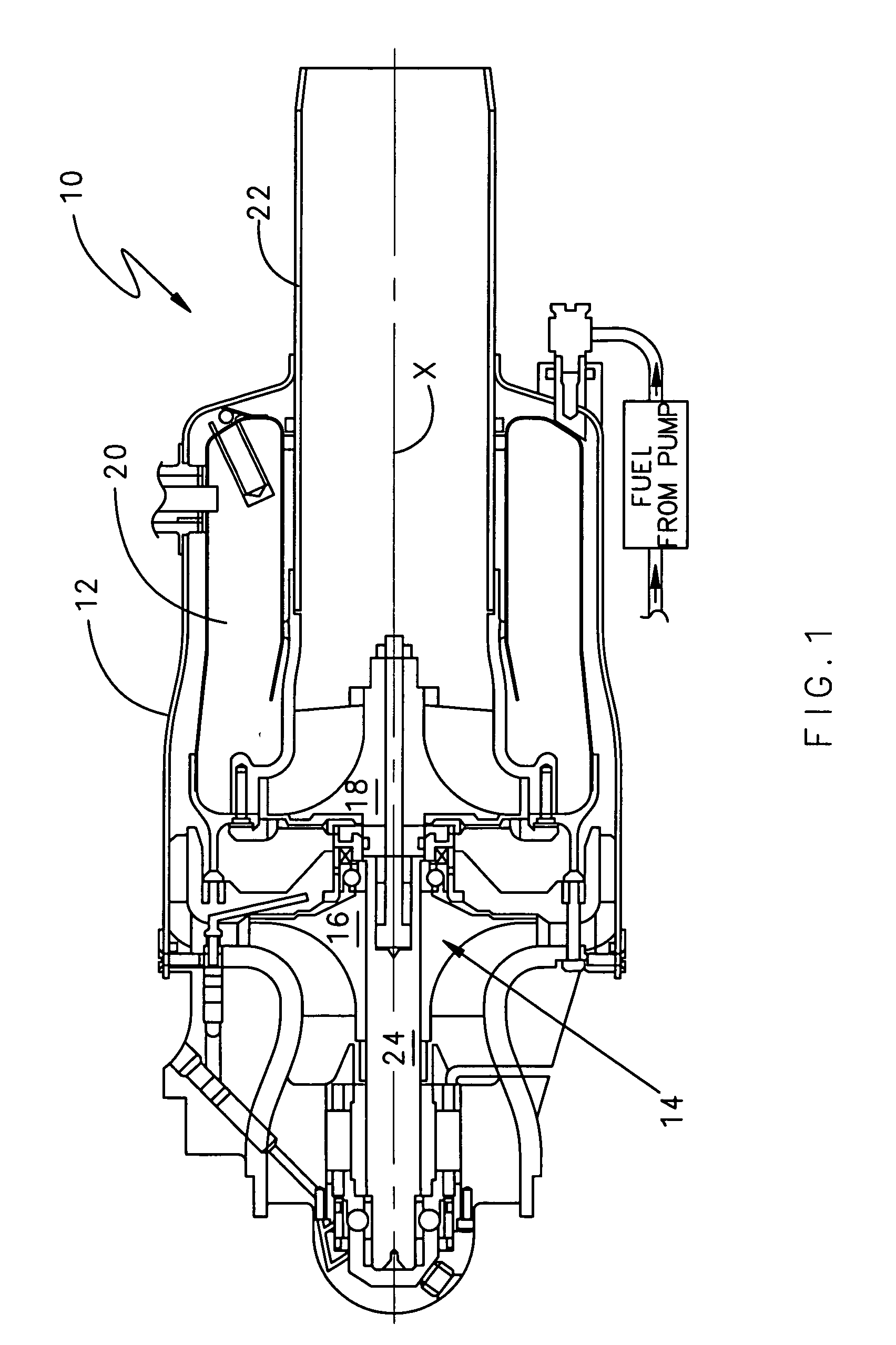
[0018]FIG. 1 illustrates a general sectional schematic view of a gas turbine engine 10 which generally includes a housing 12, a rotor system 14 which rotates about a longitudinal axis X, a combustion system 20 and an exhaust 22. The rotor system includes a compressor rotor 16 and a turbine rotor disc 18 mounted to a rotor shaft 24. In the illustrated rotor configuration, the rotor system 14 includes a ceramic turbine rotor disc 18 mounted to a metallic rotor shaft 24 at a coupling 26. It should be understood that although a gas turbine engine is illustrated in the disclosed embodiment, various shafts coupling segments for various applications will also benefit from the present invention.

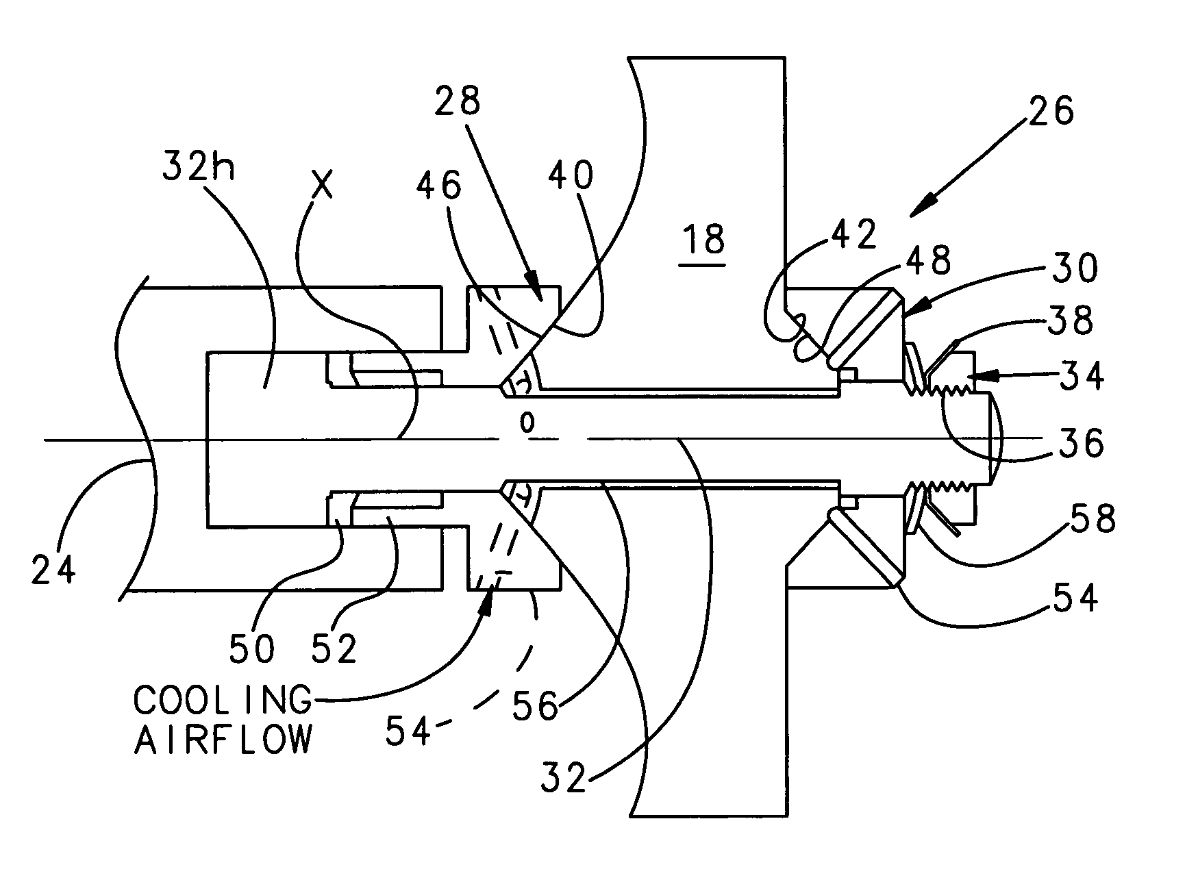
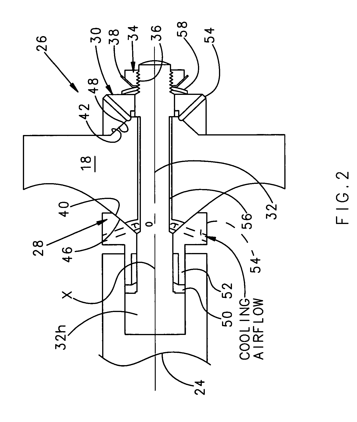
[0019] Referring to FIG. 2, the coupling 26 includes a first wedge clamp 28 and a second wedge clamp 30 mounted together by a tie-bolt 32. A fastener 34 such as a nut engages a threaded end segment 36 of the tie-bolt 32 to sandwich the ceramic turbine rotor disc 18 between the wedge clamps 28, 30. P...


PUM


Abstract

A mechanical coupling for coupling a ceramic disc member to a metallic shaft includes a first wedge clamp and a second wedge clamp. A fastener engages a threaded end of a tie-bolt to sandwich the ceramic disc between the wedge clamps. An axial spring is positioned between the fastener and the second wedge clamp to apply an axial preload along the longitudinal axis. Another coupling utilizes a rotor shaft end of a metallic rotor shaft as one wedge clamp. Still another coupling includes a solid ceramic rotor disc with a multiple of tie-bolts radially displaced from the longitudinal axis to exert the preload on the solid ceramic rotor disc.

Description

[0001] This invention was made with government support under U.S. Department of Energy Contract No. DE-FC26-00CH11060 (formerly DE-FC36-00CH11060 and DE-FC02-00CH11060). The government therefore has certain rights in this invention.BACKGROUND OF THE INVENTION [0002] The present invention relates to a rotor disc to shaft coupling, and more particularly to an axial mechanical coupling between a ceramic turbine rotor and a metal shaft. [0003] Turbine inlet temperature strongly influences the thermal efficiency of a gas turbine: higher turbine inlet temperature generally leads to more thermally efficient gas turbines. However, higher turbine inlet temperature requires temperature and oxidation resistant materials such as ceramics. These components include ceramic turbine rotors that are typically attached to a metal shaft such that power is transmitted from the turbine rotor to a compressor rotor. [0004] Connecting the ceramic turbine rotor to a metal shaft requires particular structura...

Claims


Application Information

Patent Timeline
IPC IPC(8): F04D29/00
CPCF01D5/025F05B2260/301F05D2250/292F05D2250/232F05D2250/131
Inventor SHI, JUNBOMBARA, DAVIDGREEN, KEVIN E.BIRD, CONNICHOLOWCZAK, JOHN
Owner HAMILTON SUNDSTRAND CORP
Why Eureka
Try Eureka