Laser Probe Assembly with Laser Light Source Connector and Electronic Identification Connector

a technology of laser light source and laser probe, which is applied in the field of optical fiber surgical instruments, can solve the problems of inconvenient light source and prior art laser light sour

Inactive Publication Date: 2007-10-11
SYNERGETICS
View PDF11 Cites 39 Cited by
  • Summary
  • Abstract
  • Description
  • Claims
  • Application Information

AI Technical Summary

Benefits of technology

[0009]The present invention overcomes the inconveniences associated with the prior art laser light source described above by providing an optic fiber surgical instrument that includes an optic fiber connector that can be connected to the female connector of the laser light source, and also includes a separate auxiliary connector that can be grounded to the housing of the laser light source to create an electronic circuit between the female connector of the laser light source and the housing of the laser light source that includes an electronic device recognized by the controls of the laser light source. In addition, the auxiliary connector is provided with circuitry that enables the optic fiber surgical instrument to be used with the laser light source that only recognizes encoded surgical instruments where the laser light source has been wired incorrectly during manufacturing.

Problems solved by technology

The above-described prior art laser light source that can only be used with a set of microsurgical instruments that is recognized by the light source has been found to be inconvenient when it is desirable to use other types of surgical instruments with the particular laser light source.

Method used


Image

  • Laser Probe Assembly with Laser Light Source Connector and Electronic Identification Connector
  • Laser Probe Assembly with Laser Light Source Connector and Electronic Identification Connector
  • Laser Probe Assembly with Laser Light Source Connector and Electronic Identification Connector

Examples


second embodiment

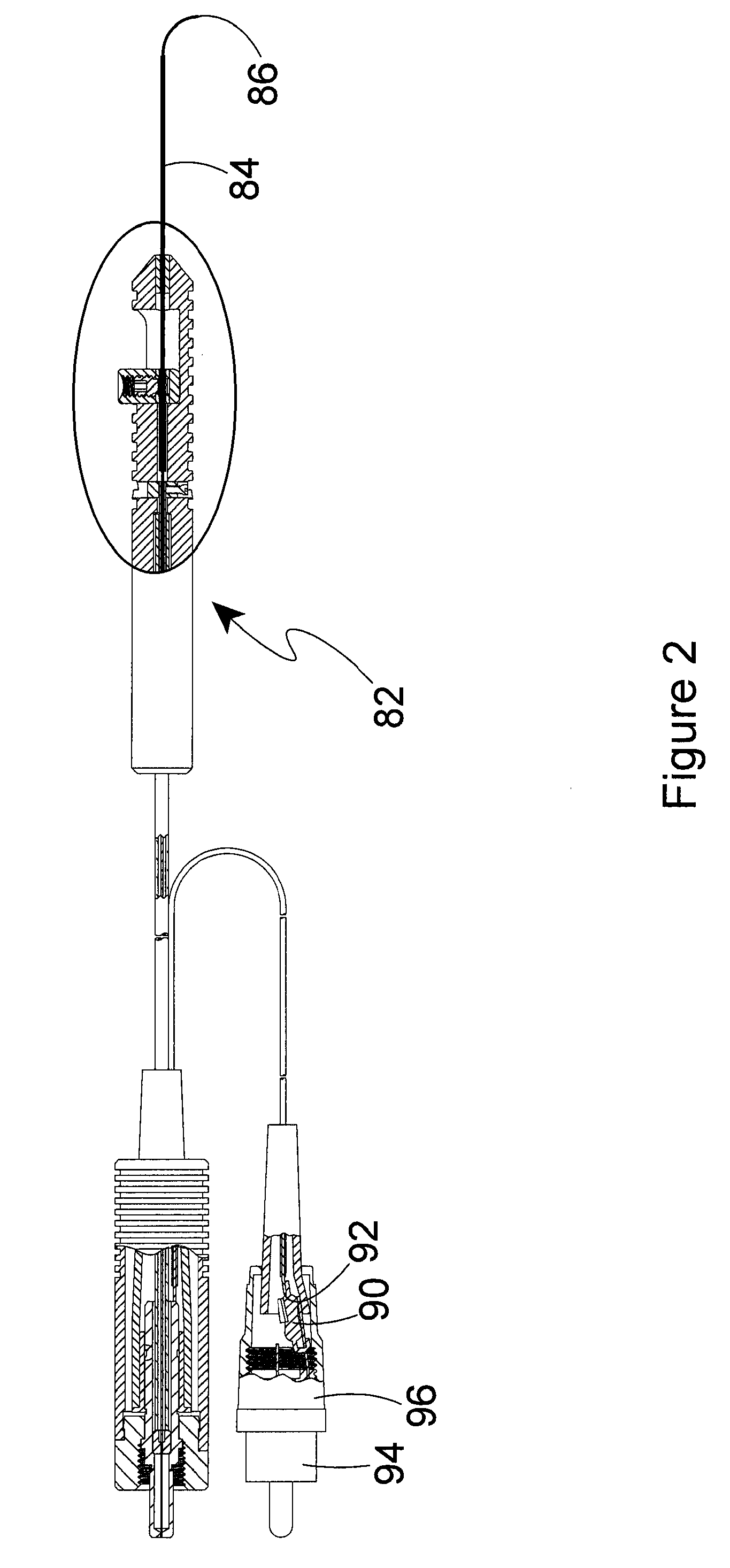
[0030]FIG. 2 shows the instrument of the invention. In the embodiment of FIG. 2, the laser probe 82 is slightly different than the laser probe 12 of FIG. 1. The laser probe 82 of FIG. 2 is of a type described earlier, where the instrument tip 84 can be selectively moved relative to the optic fiber distal end 86. This enables the optic fiber distal end 86 to be moved through a gradual bend, and enables the directing of the laser light emitted from the optic fiber distal end. Instruments of this type are known in the art.

[0031]The primary difference between the embodiment of FIG. 2 and the embodiment of FIG. 1 is the repositioning of the electrical identification device 90 to the proximal end 92 of the electrical conductor wire. The electrical identification device 90 is connected between the wire proximal end 92 and the RCA connector sleeve 94 of the auxiliary connector 96. As in the first described embodiment, the electrical identification device 90 is operatively electrically conne...

third embodiment

[0032]FIG. 3 shows the instrument that is similar to that of FIG. 1. In the embodiment of FIG. 3, the electrical identification device 100 is moved from the length of the electrical conductor 102 into the interior of the auxiliary connector 104. As in the previously described embodiment, the electrical identification device 100 is operatively electrically connected to the wire proximal end 106 of the electrical conductor 102. However, the embodiment of FIG. 3 differs from that of FIGS. 1 and 2 in that the electrical identification device 100 is also operatively electrically connected to the center post 108 of the RCA auxiliary connector 104, and to the sleeve 110 of the RCA auxiliary connector. The electrical identification device 100 is operatively electrically connected through a first diode 112 to the auxiliary connector center post 108, and is operatively electrically connected through a second diode 114 to the auxiliary connector sleeve 110. FIG. 4 shows a schematic representat...


PUM


Abstract

An optic fiber surgical instrument is removably connectable to a surgical light source. The instrument is provided with an optic fiber connector and a separate auxiliary or electric identification connector. The optic fiber connector is removably connectable to a laser light output of a laser light source to convey the laser light through the optic fiber of the instrument, whereby manipulation of the instrument by a user can direct the laser light to a surgical site. The auxiliary connector is connectable to a ground connection of the surgical light source to establish an electric circuit through the instrument and the surgical light source, whereby an electrical identification device on the instrument identifies the instrument for the surgical light source.

Description

[0001]This patent application claims the benefit of provisional patent application No. 60 / 791,171, filed on Apr. 11, 2006, and provisional patent application Ser. No. 60 / 858,053, filed on Nov. 10, 2006.BACKGROUND OF THE INVENTION[0002]1. Field of the Invention[0003]The present invention pertains to an optic fiber surgical instrument that is removably connectable to a surgical light source. In particular, the instrument is provided with an optic fiber connector and a separate auxiliary or electric identification connector. The optic fiber connector is removably connectable to a laser light output of a laser light source to convey the laser light through the optic fiber of the instrument, whereby manipulation of the instrument by a user can direct the laser light to a surgical site. The auxiliary connector is connectable to a ground connection of the surgical light source to establish an electric circuit through the instrument and the surgical light source, whereby an electrical ident...

Claims


Application Information

Patent Timeline
Patent Type & Authority Applications(United States)
IPC IPC(8): A61B18/18
CPCA61B18/22A61B19/44A61F9/008A61B2018/00988A61B2017/00482A61B90/90A61B2562/225A61B2562/226
Inventor SCHELLER, GREGG D.
Owner SYNERGETICS
Why Eureka
Try Eureka