
Intrapericardial lead

a pericardial lead and lead technology, applied in the field of intrapericardial leads, can solve the problems of high patient morbidity, trauma and pain, and difficulty in quick and easy attachment, and achieve the effect of small frontal area and convenient delivery into the pericardial spa

Inactive Publication Date: 2007-10-11
PACESETTER INC
View PDF73 Cites 102 Cited by
  • Summary
  • Abstract
  • Description
  • Claims
  • Application Information

AI Technical Summary

Benefits of technology

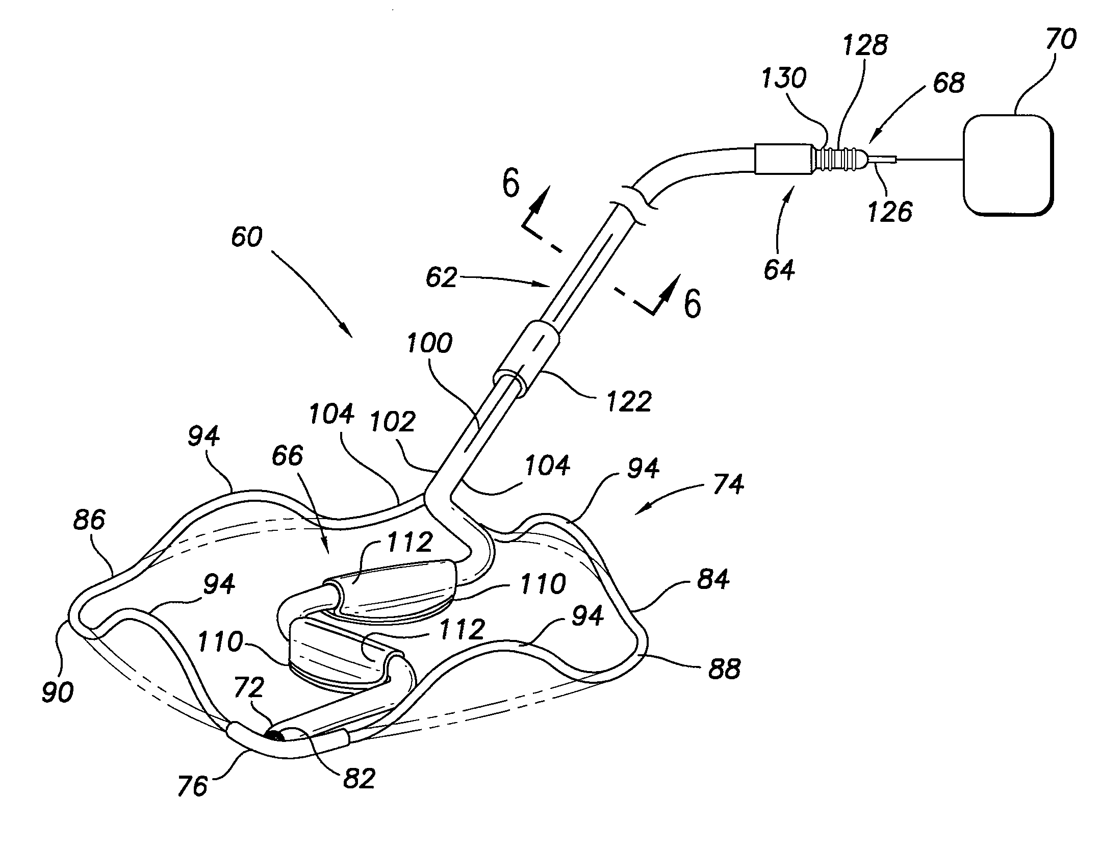
[0010]In accordance with one specific, exemplary embodiment of the present invention, there is provided a cardiac lead comprising a lead body having a proximal portion and a flexible, pre-curved distal end portion. The distal end portion carries at least one electrode assembly containing an electrode adapted to engage pericardial tissue. The distal end portion further carries a pre-curved flexible wire member having ends attached to spaced apart points along the distal end portion of the lead body, the flexible wire member h

Problems solved by technology

Furthermore, the coronary veins dictate the implant location of the electrode, which can make optimal left side lead placement impossible and may cause long and unpredictable implant times. In addition, approximately 10% of the patient population is unable to receive this type of lead due to vasculature anomalies.
Such placement techniques have disadvantages including the relatively large incisions needed to gain access to the thoracic cavity and to the heart; the difficulty of quickly and easily attaching the lead; the high rate of patient morbidity, trauma and pain; the tendency to require longer in-patient recovery times; and the unattractiveness of the scars left by the procedure.

Method used


Image

  • Intrapericardial lead
  • Intrapericardial lead
  • Intrapericardial lead

Examples


Embodiment Construction

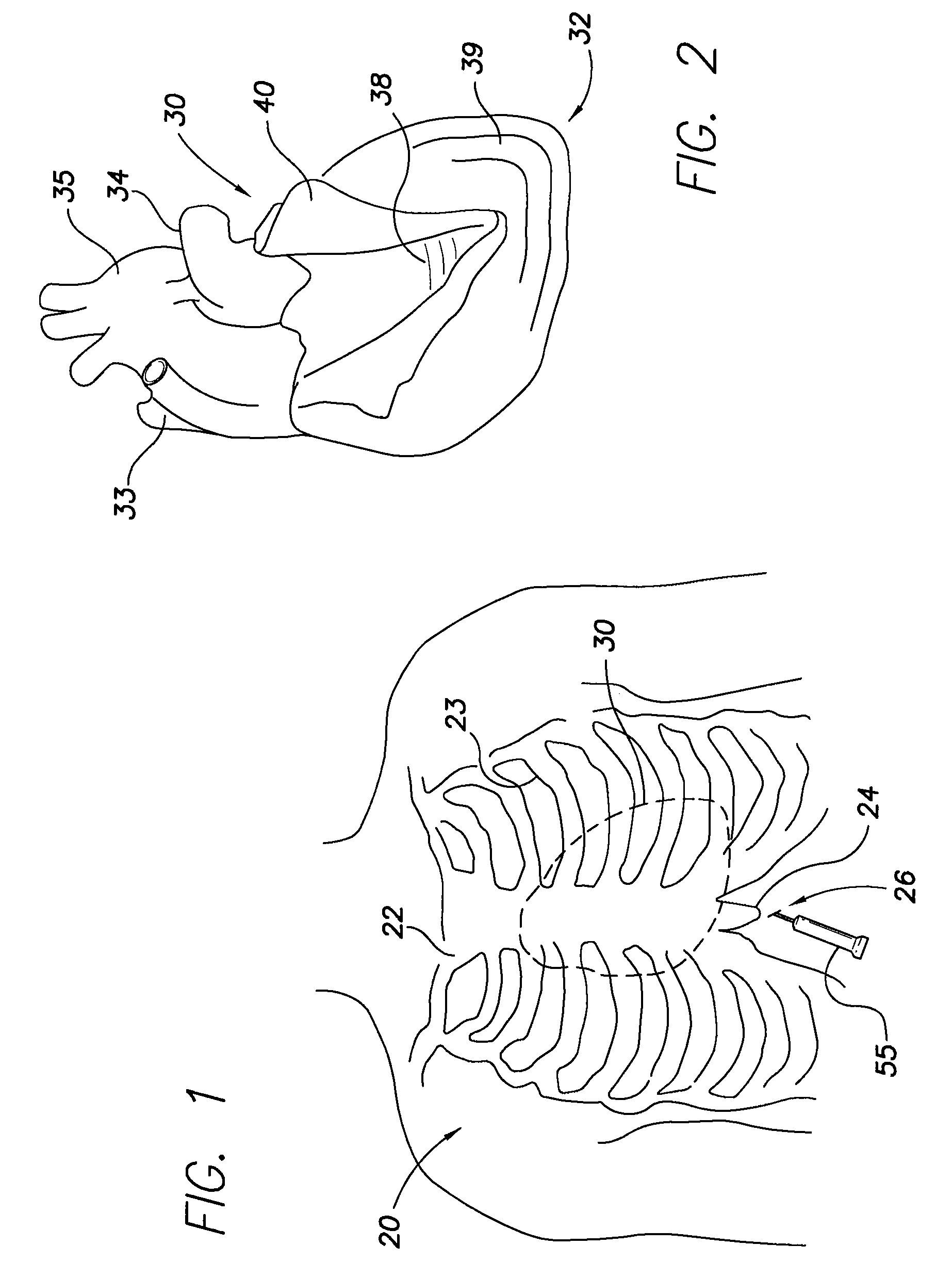
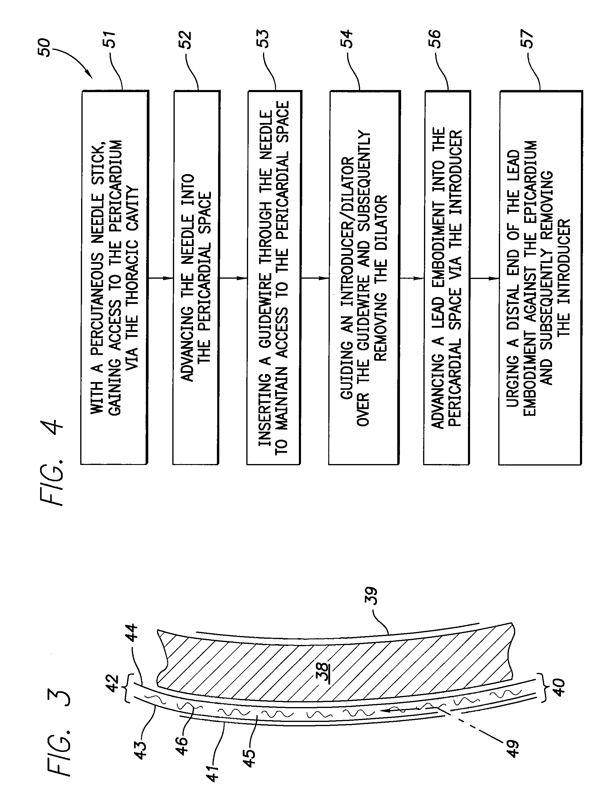
[0029]The present invention is directed to cardiac lead embodiments that facilitate and enhance the accurate placement (and monitoring of that placement) of medical electrodes. Although the lead embodiments may be used in a variety of medical procedures, they are especially suited for installation as a cardiac lead into the pericardial space of the heart. This installation may be made, for example, via percutaneous subxiphoid procedures. In order to best understand the novel structure of these embodiments, their placement and their subsequent use, a description of the structure is preceded by the following review of chest and heart structures.

[0030]FIGS. 1 and 2, respectively, illustrate these structures and, in particular, the reference numeral 20 in FIG. 1 schematically illustrates the human chest and shows the sternum 22 and the ribs 23 which attach to the sternum. The ribs and the sternum form a “rib cage” which provides a protective covering around the heart, lungs and other vi...


PUM


Abstract

The intrapericardial lead includes a lead body having a proximal portion and a flexible, pre-curved distal end portion. The distal end portion carries at least one electrode assembly containing an electrode adapted to engage pericardial tissue. The distal end portion further carries a pre-curved flexible wire member having ends attached to spaced apart points along the distal end portion of the lead body, the flexible wire member having a normally expanded state wherein an intermediate portion of the wire member is spaced apart from the distal end portion, and a generally straightened state wherein the wire member and the distal end portion are disposed in a more parallel, adjacent relationship so as to present a small frontal area to facilitate delivery into the pericardial space. The wire member re-expands to its normal state after delivery into the percaridal space to anchor the distal end portion of the lead body relative to the pericardial tissue.

Description

CROSS REFERENCES TO RELATED APPLICATIONS[0001]This application claims the benefit of U.S. Provisional Application Ser. No. 60 / 791,523 filed Apr. 11, 2006.FIELD OF THE INVENTION[0002]The present invention relates generally to cardiac leads carrying electrodes for electrically stimulating body tissue and / or for sensing the electrical activity of such tissue. More particularly, the invention relates to cardiac leads configured for secure placement within the intrapericardial space of the human heart.DESCRIPTION OF THE RELATED ART[0003]Implantable medical devices, for example, pacemakers and cardio-defibrillators, utilize leads to form the electrical connection between a device pulse generator and the heart tissue that is to be stimulated. As is well known, the leads connecting such devices with the heart may be used for pacing or for sensing electrical signals produced by the heart or for both pacing and sensing in which case a single lead serves as a bidirectional pulse transmission l...

Claims


Application Information

Patent Timeline
IPC IPC(8): A61N1/05
CPCA61N1/057A61N1/059A61N2001/058A61N1/0587
Inventor MORGAN, KEVIN L.CONGER, STEVEN R.BARLOW, ANNAROSENBERG, STUARTHOU, WENBOYANG, MICHAELWILLIAMS, SHELDON
Owner PACESETTER INC
Learn More