Driving support method and driving support device

a technology of supporting device and driving support, which is applied in the direction of navigation instruments, instruments, transportation and packaging, etc., can solve the problems of lowering image quality, accumulating filter and rotation processing errors or the like, introducing and accumulating errors, etc., and achieve good image quality

a technology of supporting device and driving support, which is applied in the direction of navigation instruments, instruments, transportation and packaging, etc., can solve the problems of lowering image quality, accumulating filter and rotation processing errors or the like, introducing and accumulating errors, etc., and achieve good image quality

US20070239357A1Inactive Publication Date: 2007-10-11AISIN AW CO LTD

Image

  • Driving support method and driving support device
  • Driving support method and driving support device
  • Driving support method and driving support device

Examples


Embodiment Construction

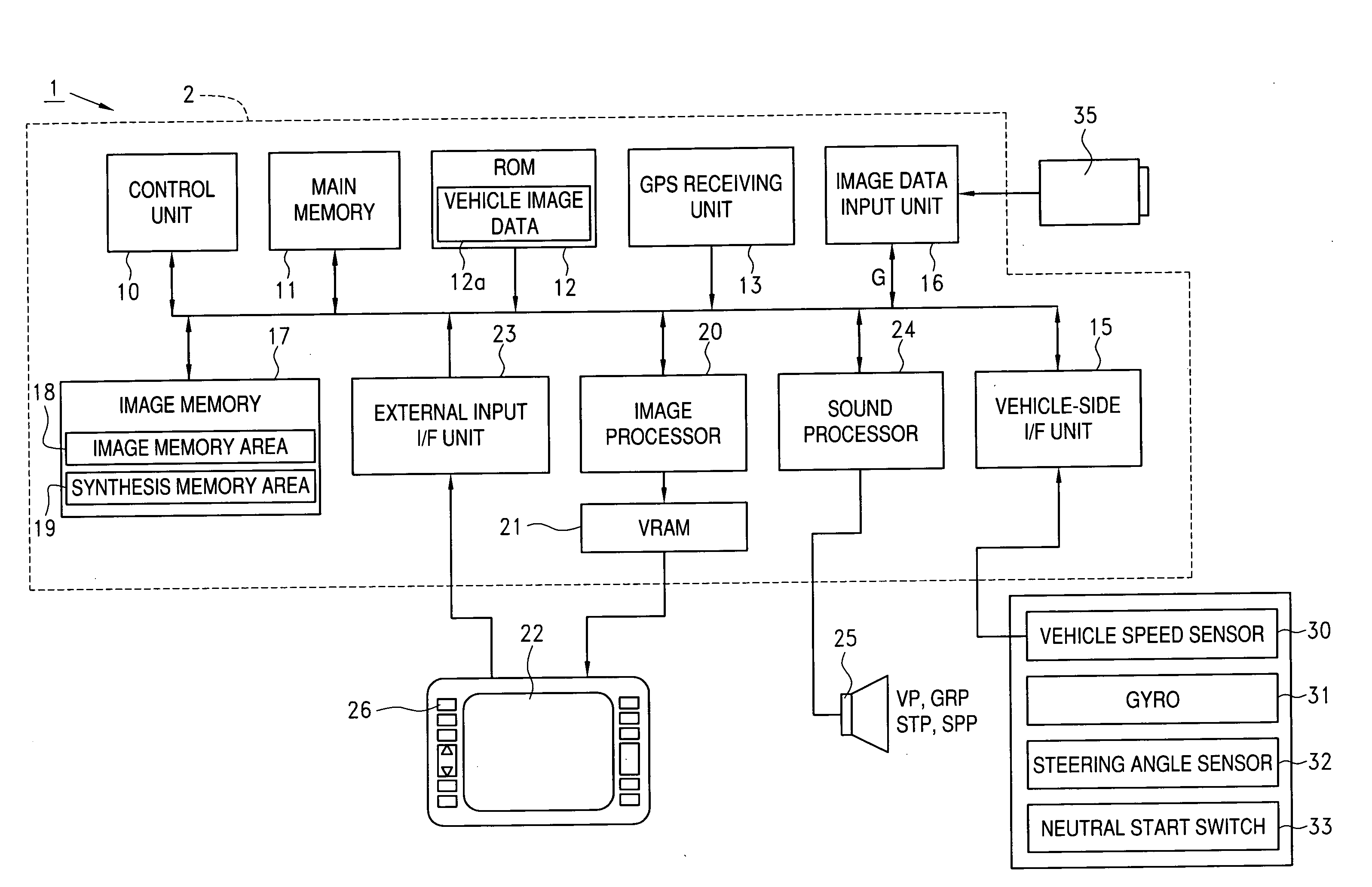
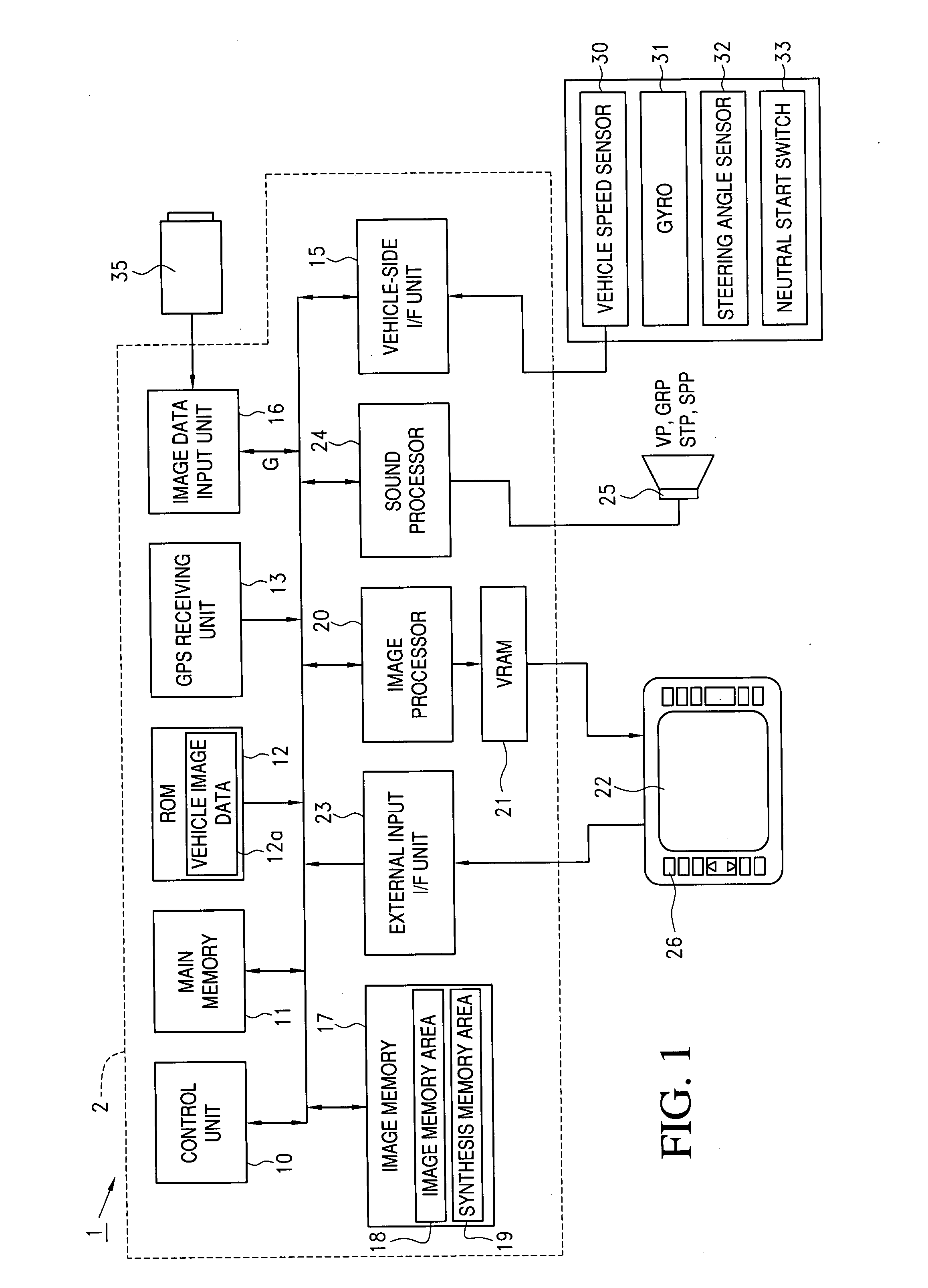
[0040]As discussed below, an exemplary embodiment of a driving support method and a driving support device will be described with reference to FIGS. 1 to 18. FIG. 1A is a block diagram that explains the structure of a parking assist system 1 mounted in an automobile.

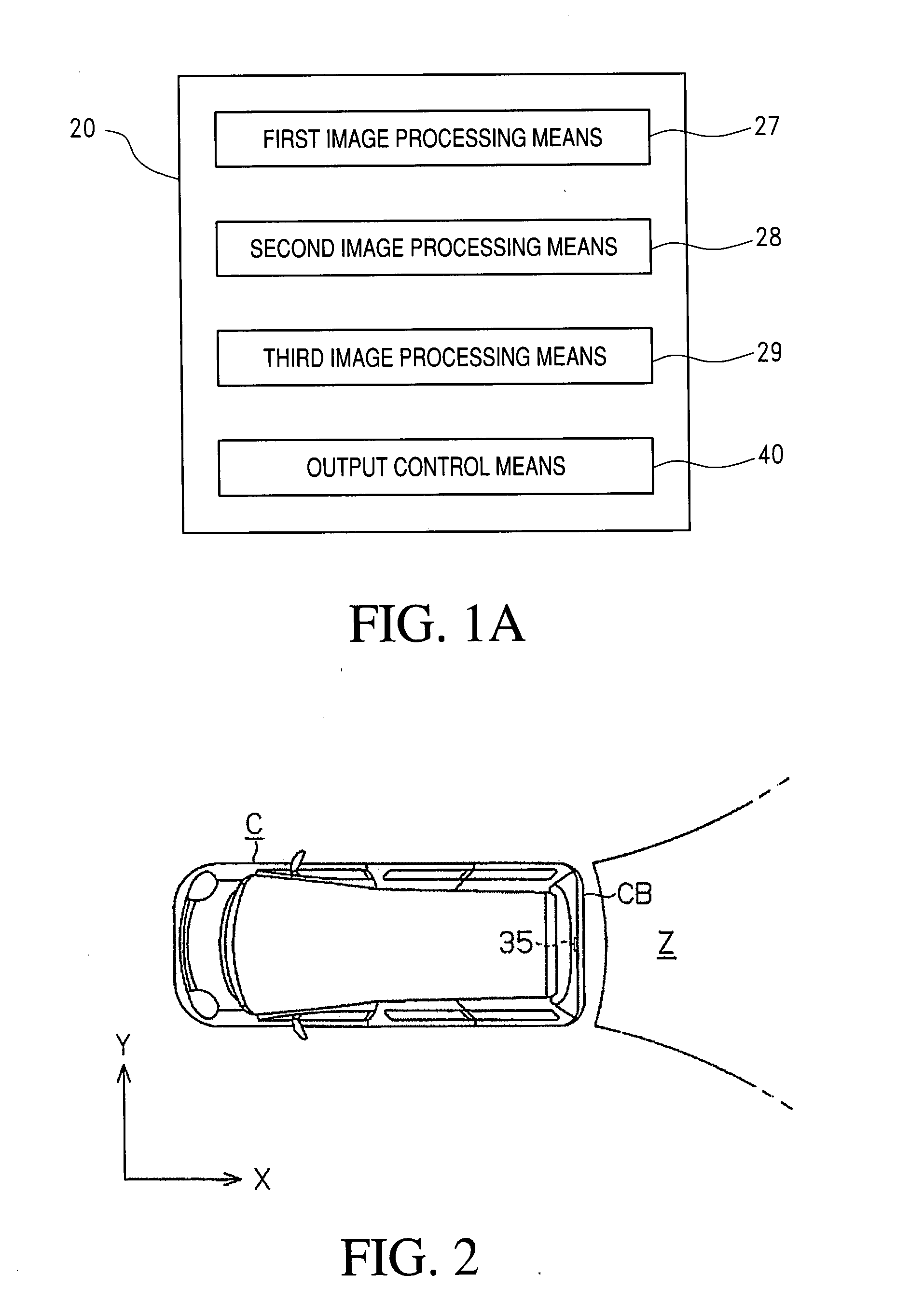
[0041]Referring to FIG. 1A, the parking assist system 1 includes: a parking assist unit 2, which acts as a driving support device; a display 22, which acts as a display means for showing various screens; a speaker 25 that outputs warning sounds and speech guidance; and a back monitor camera (hereinafter simply referred to as a camera 35) which acts as an imaging device. As FIG. 2 illustrates, the camera 35 is installed on or near the rear end CB of a vehicle, such as a rear door of a vehicle C, such that an optical axis thereof faces diagonally downward. The camera 35 may be a digital camera that produces a color image. Of course, any other suitable type of imaging device may be used. The camera 35 may also include: an o...


PUM


Abstract

A parking assist unit includes an image processor for setting a reference position of a vehicle, and an image data input unit for inputting image data from a camera provided on the vehicle. The image processor performs rotation processing on the image data to generate recorded data, based on a relative position with respect to the reference position of the vehicle during imaging. In addition, the recorded image data generated is accumulated in a corresponding pixel area within a synthesis memory area. Furthermore, the recorded image data accumulated is used to generate synthesized data, and such synthesized data is shown on a display.

Description

INCORPORATION BY REFERENCE[0001]The disclosure of Japanese Patent Application No. 2006-094065 filed on Mar. 30, 2006 including the specification, drawings and abstract is incorporated herein by reference in its entirety.BACKGROUND[0002]1. Field of the Invention[0003]The present invention relates to a driving support method and a driving support device.[0004]2. Description of the Related Art[0005]Conventional devices for supporting safe driving include a navigation apparatus that shows a background image of the vehicle's surroundings on a display. Such an apparatus inputs a picture signal from an onboard camera mounted at the rear end of the vehicle, and outputs a background image based on that picture signal to a display provided near the driver's seat.[0006]Japanese Patent Application Publication No. JP-A-2002-373327 proposes an image processing device that collects image data input from an onboard camera when a parking operation is performed, and uses the collected image data to p...

Claims


Application Information

Patent Timeline
11 Oct 2007
Publication
US20070239357A1
IPC
G01C21/00
CPC
B62D15/028; B62D15/027
Inventors
MORI, TOSHIHIRO; KUBOTA, TOMOKI