Flexible pickup lips for use with fixed vacuum shoes on self-contained and propelled carpet cleaning equipment

a technology of fixed vacuum shoes and pickup lips, which is applied in the direction of carpet cleaners, cleaning equipment, road cleaning, etc., can solve the problems of limiting the ability of the machine to maneuver, limiting the doorway that the machine can pass through, and affecting the cleaning effect of the surface, so as to increase the efficiency of suction and speed up the drying time , the effect of increasing the battery li

Inactive Publication Date: 2007-10-18
KARCHER NORTH AMERICA INC
View PDF11 Cites 12 Cited by
  • Summary
  • Abstract
  • Description
  • Claims
  • Application Information

AI Technical Summary

Benefits of technology

[0010] It is desired to have self-propelled cleaning machines that have an increased efficiency of suction, which results in quicker drying times, increased battery life, decreased wear on a surface to be cleaned, all of which result in improved productivity and efficiency. It is thus one aspect of the present invention to provide a self-propelled cleaning apparatus comprising a vacuum shoe that is more efficient and easier to clean than prior used vacuum shoes. A self-propelled cleaning apparatus having a more efficient vacuum shoe provides for several advantages.
[0011] One such advantage that may be provided by an apparatus with an efficiently gliding vacuum shoe is decreased amount of required power needed to propel the equipment, thus resulting in increased run time for some cleaning machines. A decrease in required power consumption may also result in the use of a smaller battery or power source on the cleaning machine, which in turn may result in the use of a lighter battery, more efficient propulsion systems, etc. A lighter battery translates to a lighter cleaning machine, which corresponds to decreased wear on a surface to be cleaned. Economic efficiencies in overall machine production costs may also be realized.
[0012] Another advantage that may be offered by embodiments of the present invention is decreased drying times may be realized. The suction rate of an efficient vacuum shoe is greater than the suction rate afforded by vacuum shoes used in the prior art. With an increased suction rate, quicker drying times result because more debris and water may be picked up with a single pass of the vacuum shoe than would have otherwise been picked up with machines of the prior art. The result is quicker cleaning times, because fewer passes with the cleaning machine is required. The bottom line is that after a cleaning apparatus employing the vacuum shoe of the present invention has cleaned an area, one does not have to wait for an extraordinarily long amount of time before the surface can be walked on again.
[0013] Another aspect of the present invention is to provide a selectively attachable gliding surface that may be fastened to a prior art vacuum shoe. An easily detachable and re-attachable gliding member provide for easy access to clear blockages from the main vacuum shoe since the gliding member may be easily removed. Moreover, smaller slots increase the suction forces at the surface without requiring more suction power. Additionally, the gliding surface helps to reduce the impact forces applied to the vacuum shoe by transitions in the floor surface, which in turn helps to decrease the amount of maintenance required for the vacuum shoe and the cleaning apparatus. The gliding member may be easily and relatively cheaply replaced by a new gliding member after it has been worn out by use, whereas a vacuum shoe is expensive and sometimes difficult to replace after it has been worn out.
[0014] In accordance with one embodiment of the present invention, a cleaning apparatus is provided. The cleaning apparatus comprises a vacuum shoe comprising a shoe housing have a proximal end a distal end with a vacuum chamber there between. The proximal end is defined by an opening that is adapted interface with a gliding member. The distal end is adapted to interface with a hose and / or vacuum source on the cleaning apparatus. The gliding member comprises a surface that easily glides across a surface to be cleaned. For example, the gliding surface intersects the surface to be cleaned at an angle that has a decreased drag coefficient compared to vacuum shoes of the prior art. An angle of intersection typically is defined by the angle between the intersecting surface and the surface to be cleaned. Suitable angles of intersection include, but are not limited to, between about 2° and about 80°. The shallower the angle of intersection the more easily the vacuum shoe can traverse the surface to be cleaned. Additionally, the outer surface of the gliding member extends from the intersection point outwardly (in a general direction of travel) such that the incident angle between the outer surface and the surface to be cleaned increases such that the chances of intersecting the surface to be cleaned with an abrupt surface is decreased. Further, the gliding member is preferably made of a material that moves over a surface to be cleaned much more efficiently and effectively than materials used on prior art vacuum shoes. Examples of suitable materials include, but are not limited to, Delrin®, Teflon®, and other materials having a low coefficient of friction.

Problems solved by technology

Maintaining the cleanliness of these surfaces, especially in high-volume areas, in commercial, industrial, institutional, and public buildings is an on-going and time consuming process.
These characteristics limit the machines ability to maneuver and further limit the doorway that the machine can pass through.
Unfortunately, these previously mentioned types of cleaning devices have drawbacks.
For example, they are not as efficient as possible.
The drag created by the vacuum shoe is often excessive, mainly due to the weight of the machine, the amount of pressure required to maintain a vacuum seal to the floor, and drag characteristics of the componentry that actually contacts the surface to be cleaned.
Additionally, typical vacuum shoes tend to vibrate at higher cleaning speeds.
This additional vibration may lead to more mechanical failures through the life of the machine.
Heavy equipment, such as ride-on cleaners, also tend to roll the carpet forward during cleaning, which is undesirable because if the carpet is pushed in the same direction a number of times and rolled forward in that same direction, the carpet in that area may become irreversibly ruined.
A major drawback to the vacuum shoe design shown in FIG. 1, however, is that the housing 102 intersects the floor surface abruptly, and typically is made with a material that is not specifically designed to effortlessly glide over wet carpeting, etc.
Thus, as the vacuum shoe 100 is moved forward and backwards in the direction of the depicted arrows 109, excessive drag forces are created on the vacuum shoe 100, resulting in undesired efficiency losses.
These efficiency losses contribute to both slower overall cleaning of a surface, as well as, increased power usage by the cleaning machine.
If more suction is required, then a larger vacuum motor may be required, which further increases the weight of the cleaning machine.
Moreover, in the event that a smaller vacuum motor is used in an attempt to keep the cleaning machine weight at a reasonable level, there is a chance that the vacuum motor may not be capable of supplying the required suction for adequate pickup.
Although used in hand-held wands and other hand-held cleaning devices, the inventions claimed in this invention have not been adapted for use in ride-on or walk-behind self-propelled cleaning machines.
The extra weight and power of a ride-on cleaner creates many complicating issues.
For example, typical vacuum shoes have abrupt edges that can damage floor transitions (i.e., a transition from one type of carpet to another) and the additional weight of the ride-on cleaner causes these transitions to be damaged over time.
Furthermore, when typical vacuum shoes get caught on these transitions, the forces applied to the machine may cause further damage to other machine parts.
Moreover, access to a vacuum shoe is much more difficult than with a hand-held cleaning wand making cleaning and maintenance a difficult task.
The gliding member may be easily and relatively cheaply replaced by a new gliding member after it has been worn out by use, whereas a vacuum shoe is expensive and sometimes difficult to replace after it has been worn out.

Method used


Image

  • Flexible pickup lips for use with fixed vacuum shoes on self-contained and propelled carpet cleaning equipment
  • Flexible pickup lips for use with fixed vacuum shoes on self-contained and propelled carpet cleaning equipment
  • Flexible pickup lips for use with fixed vacuum shoes on self-contained and propelled carpet cleaning equipment

Examples


Embodiment Construction

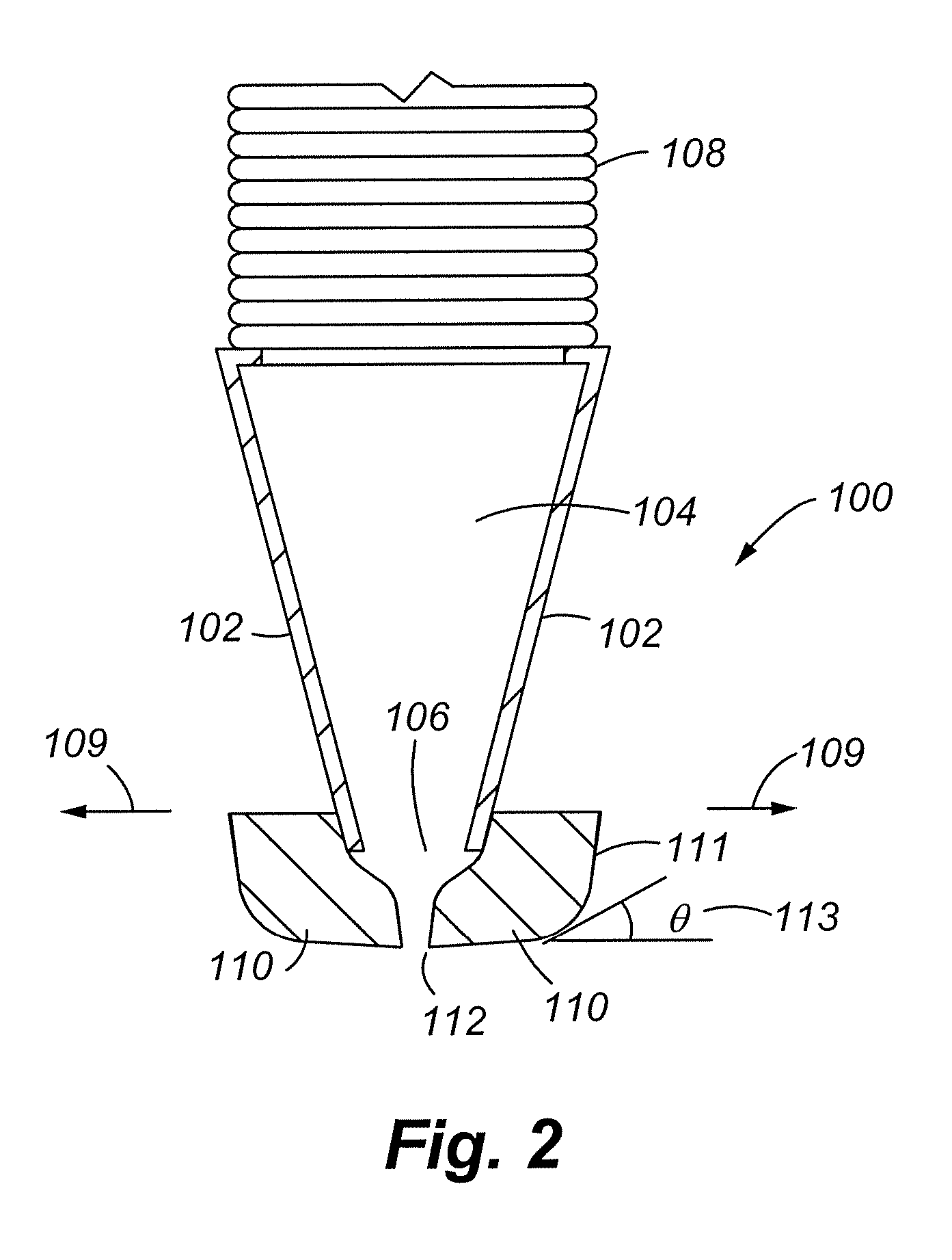
[0026] Referring initially to FIG. 2, an exemplary vacuum shoe 100 will be described in accordance with at least some embodiments of the present invention. The vacuum shoe comprises a shoe housing 102 with a vacuum chamber 104 defined by the shoe housing 102. The shoe housing 102 at a first end has an opening 106 where debris and other material, including fluids, can be received. The other end of the vacuum shoe housing 102 is adapted to be connected with a hose 108 or another type of vacuum source (e.g., a vacuum motor connected to the cleaning machine). The opening 106 of the shoe housing 102 is further adapted to be interconnected to a glide member 110 or set of glide members 110. The glide members 110 may be an integral part of the housing 102 or may be selectively attached and detached from the shoe housing 102. The glide members 110 generally have a space or an opening that defines an inlet of the glide member(s) 110. This opening 112 is typically smaller than the opening 106 ...


PUM


Abstract

An improved vacuum shoe for use on a self-propelled cleaning apparatus is disclosed. Specifically, the vacuum shoe may have a gliding member either integral or connected to the shoe housing. The gliding member is designed to decrease the drag coefficient of the vacuum shoe as it traverses a surface thereby increasing the machine's efficiency and decreasing the amount of required operating power.

Description

FIELD OF INVENTION [0001] The present invention is directed toward self-contained and propelled cleaning equipment and devices, and focuses upon a vacuum shoe and / or shoe attachment is provided that improves the cleaning ability and overall functionality of the cleaning machine. BACKGROUND OF THE INVENTION [0002] Cleaning machines are used extensively for cleaning flooring surfaces comprised of carpets and other soft floor surfaces. Maintaining the cleanliness of these surfaces, especially in high-volume areas, in commercial, industrial, institutional, and public buildings is an on-going and time consuming process. There are several different mechanisms that can be employed to clean such surfaces. [0003] One such example would be self-propelled walk-behind devices, i.e., vacuums or self-cleaning carpet machines. These apparatus typically have a scrub deck followed by a vacuum shoe. The vacuum shoe has the ability to follow the path of the scrub deck as the machine changes direction....

Claims


Application Information

Patent Timeline
Patent Type & Authority Applications(United States)
IPC IPC(8): A47L7/00
CPCA47L11/30A47L11/4088A47L11/4044
Inventor PEDLAR, ROGER
Owner KARCHER NORTH AMERICA INC
Why Eureka
Try Eureka