
Protection system for a solar water heating system

a solar water heating and protection system technology, applied in the field of solar water heaters, can solve problems such as the possible compromise of solar heating systems and their associated plumbing

Active Publication Date: 2007-10-18
RHEEM AUSTRALIA PTY LIMITED
View PDF19 Cites 13 Cited by
  • Summary
  • Abstract
  • Description
  • Claims
  • Application Information

AI Technical Summary

Benefits of technology

"The present invention provides a solar water heating system that includes a water tank, a heat transfer fluid circuit with a heat exchanger, a solar collection means, and a pump. The system uses a reversible evaporable heat transfer fluid that absorbs heat from the solar collection means and transfers it to the water tank through the heat exchanger. The system has a diversion path to prevent over-temperature conditions and a valve means to control the flow of heat transfer fluid. The solar collection means can include a liquid trap to prevent gas passing through, and the heat transfer fluid can circulate therein by thermosyphoning or by a pump means. The system can have a one-way valve or a valve means to prevent flow in the opposite direction. The solar collection means can include a flat plate collector or multiple solar collection panels connected in series or parallel. The heat transfer fluid can include a specific brand or an equivalent. The system can have a simplified isolation valve or a remotely controlled isolating valve. The invention provides a more efficient and effective solar water heating system."

Problems solved by technology

In continuing to gather solar energy the solar heating system and its associated plumbing could be compromised by over heating.

Method used


Image

  • Protection system for a solar water heating system
  • Protection system for a solar water heating system
  • Protection system for a solar water heating system

Examples


Embodiment Construction

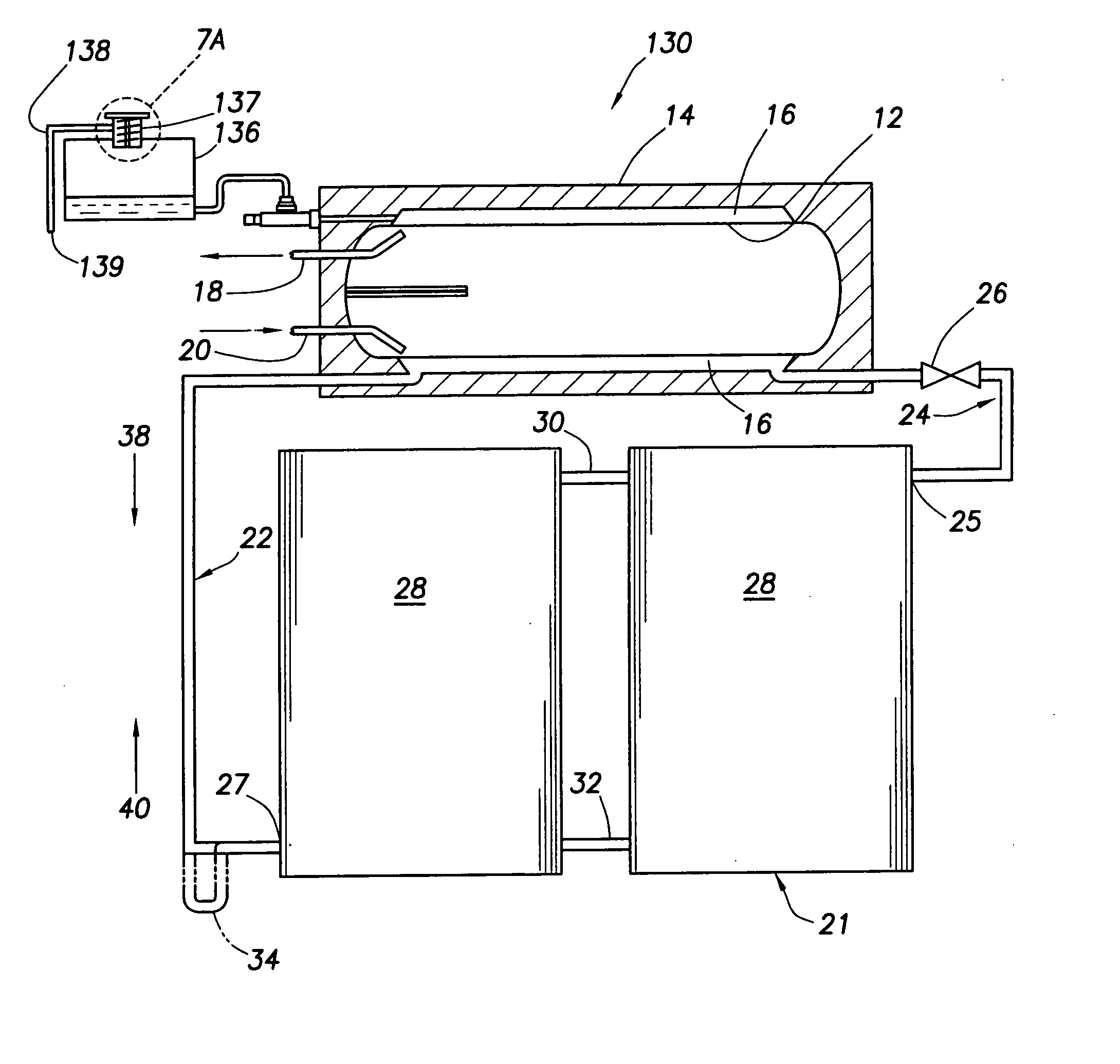
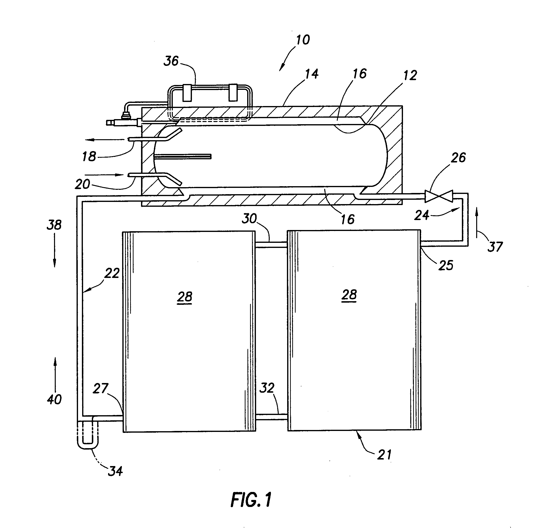
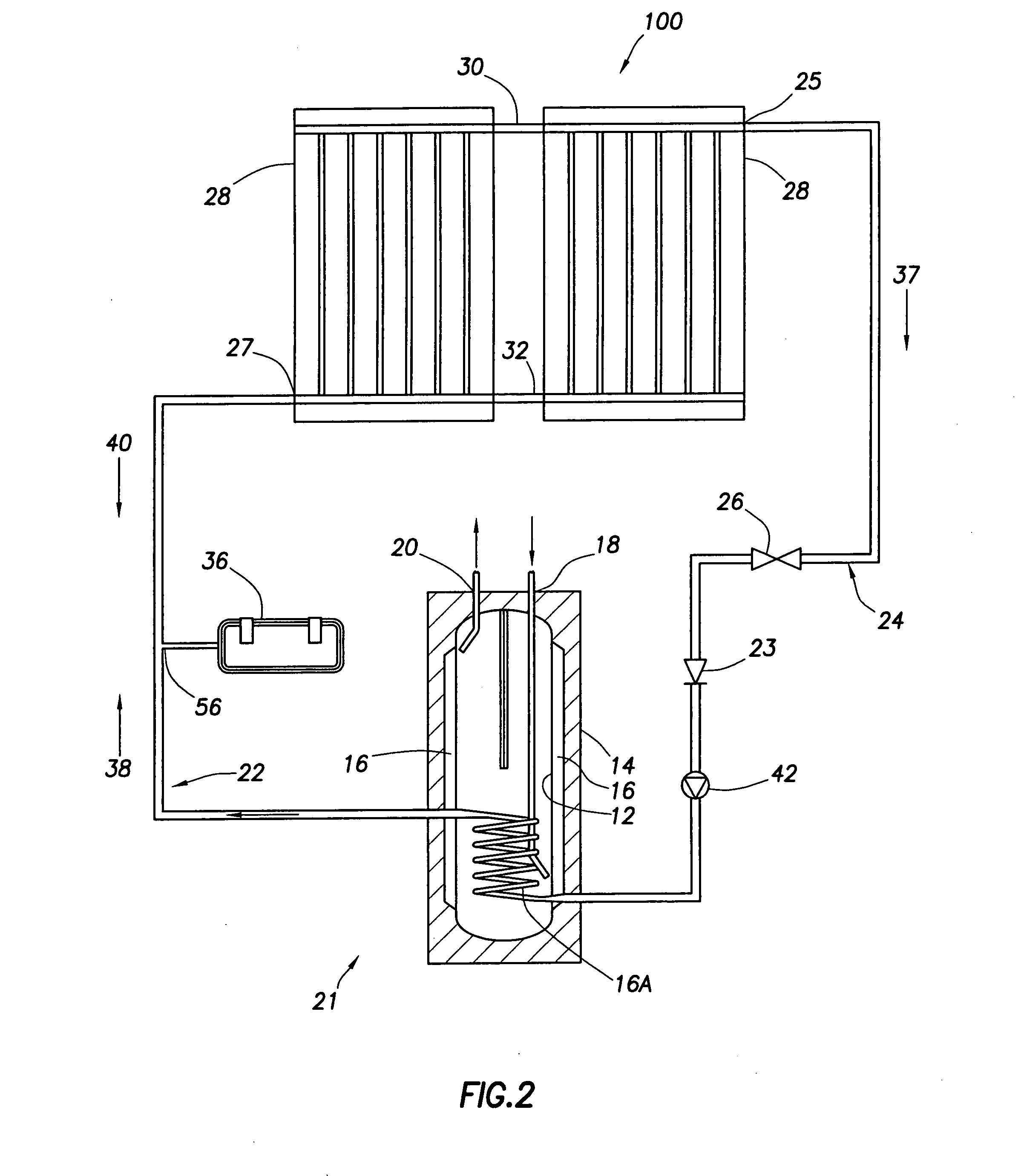
[0082] Illustrated in FIG. 1 is a solar water heating system 10 which has a water tank 12 contained within an insulated enclosure 14. The tank 12 can be of the order of 270 to 400 litres in volume. Between the exterior of the tank 12 and the insulation of the insulated enclosure 14 is an heat exchanger in the form of a jacket 16 which surrounds the water tank 12.

[0083] The water tank 12 has a hot water outlet 18 and a cold water inlet 20.

[0084] An heat transfer fluid circuit, generally designated with numeral 21, (which will contain and have flowing therein a heat transfer fluid), includes the jacket 16, an inlet connection 24 which provides fluid communication between the inlet to the jacket 16 and the outlet 25 of two connected solar collection panels 28, and an outlet connection 22 which provides fluid communication between the outlet from the jacket 16 and the inlet 27 to the solar collection panels 28.

[0085] The circuit 21 also has fluid connections 30 and 32 interconnecting...


PUM


Abstract

The present invention includes a solar water heating system including: a water tank to hold water to be heated, an heat transfer fluid circuit including an heat exchanger associated with said water tank to heat water therein, a solar collection means in communication with said heat exchanger, an inlet connection to carry heat transfer fluid from said solar collection means to said heat exchanger where said water will be heated; and an outlet connection to carry heat transfer fluid from said heat exchanger to said solar collection means where said heat transfer fluid will be heated, said heat transfer fluid circuit including a reversibly evaporable heat transfer fluid which will absorb heat from said solar collection means and which will transfer said heat to said water in said water tank by means of said heat exchanger; and an diversion path being provided in said heat transfer circuit, whereby when a portion of heat transfer fluid changes to a gaseous state in said solar collection means, heat transfer fluid in a liquid state will be forced out of said solar collection means under pressure into said diversion path.

Description

CROSS-REFERENCE TO RELATED APPLICATIONS [0001] This application is a national stage filing under Chapter II of the Patent Cooperation Treaty of International Application No. PCT / AU2004 / 000459 filed Apr. 8, 2004, which claims priority to Australian Patent Application 2003901720 filed Apr. 11, 2003; Australian Patent Application 2003906266 filed Nov. 13, 2003; and Australian Patent Application 2004900789 filed Feb. 17, 2004. The entire disclosures of these prior applications are incorporated herein by this reference.FIELD OF THE INVENTION [0002] The present invention relates to solar water heaters and in particular to solar water systems which include over-heating protection systems. BACKGROUND OF THE INVENTION [0003] As standards for plumbing products are made more stringent, there is a need to provide protection for plumbing products in a solar water heater environment, particularly once water in a tank heated by solar means has reached its desired temperature. Unlike electrical or ...

Claims


Application Information

Patent Timeline
Patent Type & Authority Applications(United States)
IPC IPC(8): F24J2/40F24D17/00F24J2/34F24J2/46
CPCF24D17/0021F24J2/345F24J2/4627Y02E10/44Y02B10/20Y02B10/70F24J2/32F24J2/463F24S40/58F24S40/53F24S60/30F24S10/95Y02E10/40
Inventor BOURKE, BRENDAN VINCENT
Owner RHEEM AUSTRALIA PTY LIMITED
Learn More