
Vehicle Wheel Comprising A Wheel Rim And Rubber Tire

a technology of rubber tire and wheel rim, which is applied in the field of vehicles, can solve the problems of difficult to have a new solid tire mounted on the rim when needed, and difficult to meet the needs of a new solid tire when needed, so as to reduce the surface pressure and avoid laborious and long handling.

Inactive Publication Date: 2007-10-18
CONTINENTAL REIFEN DEUTSCHLAND GMBH
View PDF6 Cites 19 Cited by
  • Summary
  • Abstract
  • Description
  • Claims
  • Application Information

AI Technical Summary

Benefits of technology

[0011] It has surprisingly been shown that the problem of the thermal expansion in particular can be solved in that the upper shell, like the lower shell, is composed of segments, namely of at least two segments, preferably of three to five segments. It is thus possible to get control of the thermal problems, in particular by assembling the segments of the upper shell so that expansion joints remain between the segments, which joints are able to equalize the thermal expansion.
[0014] Furthermore, an embodiment of the upper shell in segmented form offers the advantage of providing it with an axial locking, e.g., in tongue and groove form, and a radial locking which in particular has the advantage that an improper torquing of the screw joint does not lead to a breaking of the belt of the solid tire arranged on the upper shell.
[0015] Furthermore, it can be expedient to provide the radially outer contour of the upper shell axially outside with a domed shoulder so that the radially outer contour of the upper shell as a whole has the form of a saddle. An embodiment of this type has proven to be advantageous since it counteracts the stress cracks occurring with high applied axle loads in the base area of the solid tire.
[0017] In order to design the fitting of upper and lower shell as simply as possible, it can be advantageous to provide the segments respectively of the lower shell and the upper shell with an arresting system or a click system on their face edges. Hereby, e.g., a face edge can be provided with a hook-like pin that engages in a corresponding recess in an end face of another segment and locks in place there. The fitting of the lower shells onto the rim is thereby made extremely easy in that the segments of the lower shell are simply placed on the compression rubber of the rim and connected to the other segments by the arresting connection so that a laborious and lengthy handling is avoided.
[0018] In a further practical embodiment, it can be advantageous to install pressure cases of a metallic material in the segments of the upper shell or lower shell, which on the one hand reduce the surface pressure, and on the other hand provide a collision guard for the segments preferably comprising plastic and the screw heads.
[0019] In another advantageous embodiment of the invention, it can be advantageous to give the vehicle tire an antistatic finish. In particular when upper and lower shell are made of plastic, the problem can occur that a static charge of the tire can be hard to dissipate. It can hereby be provided that a metal belt of the solid tire is electrically connected to at least one screw that connects the upper and lower shell, whereby the screw is electrically connected to the rim of the vehicle wheel. A connection of this type of the belt via the screw to the rim can be made in an extremely simple manner, e.g., in that a wire is connected to the belt and to a metallic pressure case of the screw, whereby the screw can be connected to the rim via a plain washer or another wire.

Problems solved by technology

However, suitable presses for pressing solid tires onto the rims are heavy and expensive and not available everywhere, so that it is difficult to have a new solid tire mounted onto a rim when needed, since long distances to a workshop equipped with a press of this type often have to be tolerated.
The influence of heat on the construction of lower / upper shell has proven to be particularly problematic, in that, e.g., at high temperatures as a consequence of outer or inner temperature increases the upper shell has a tendency to undergo thermal expansion, through which a frictional contact between the upper and lower shell is not guaranteed in every case.

Method used


Image

  • Vehicle Wheel Comprising A Wheel Rim And Rubber Tire
  • Vehicle Wheel Comprising A Wheel Rim And Rubber Tire
  • Vehicle Wheel Comprising A Wheel Rim And Rubber Tire

Examples


Embodiment Construction

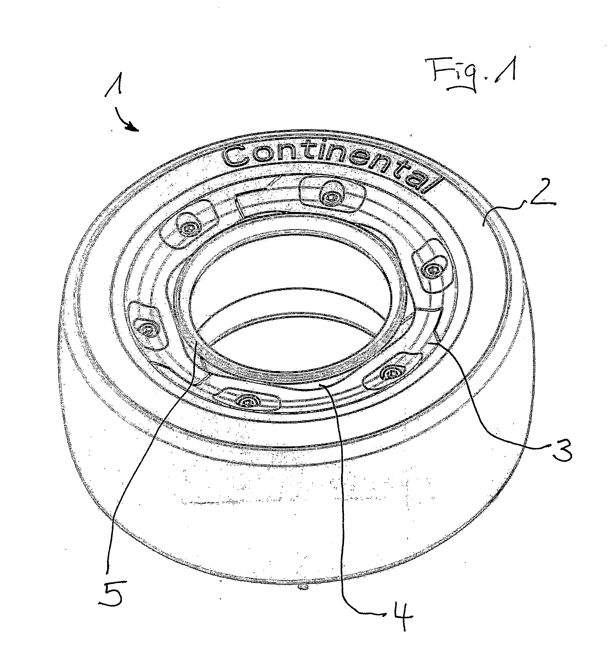
[0031]FIG. 1 shows a first exemplary embodiment of a vehicle wheel 1 according to the invention in perspective view. The vehicle wheel 1, which is preferably used for fork lift trucks, earth-moving machinery, heavy-duty vehicles or similar slow-moving vehicles with high axial load, comprises a solid tire 2 that is connected to a rim 5 by an upper shell 3 and an lower shell 4.

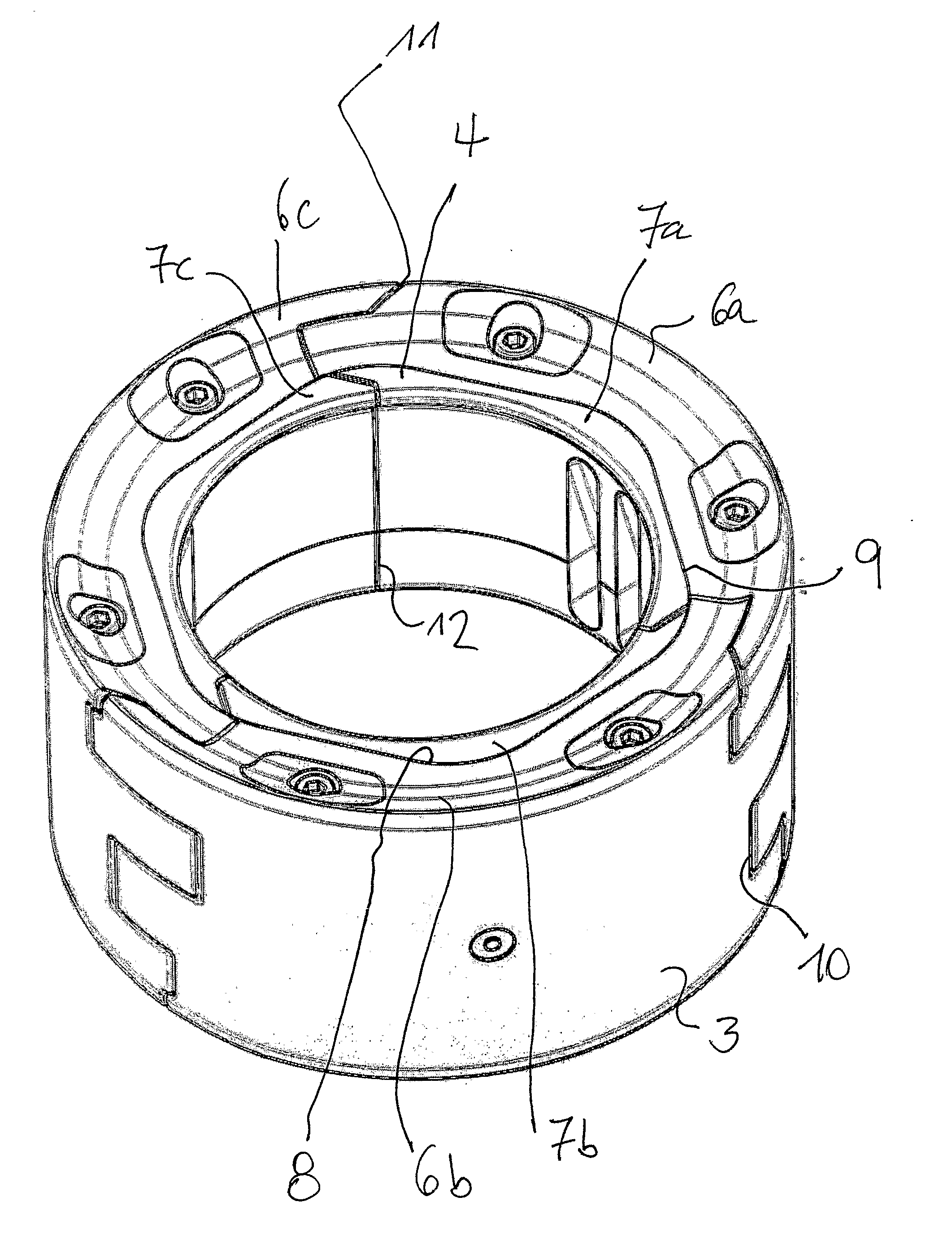
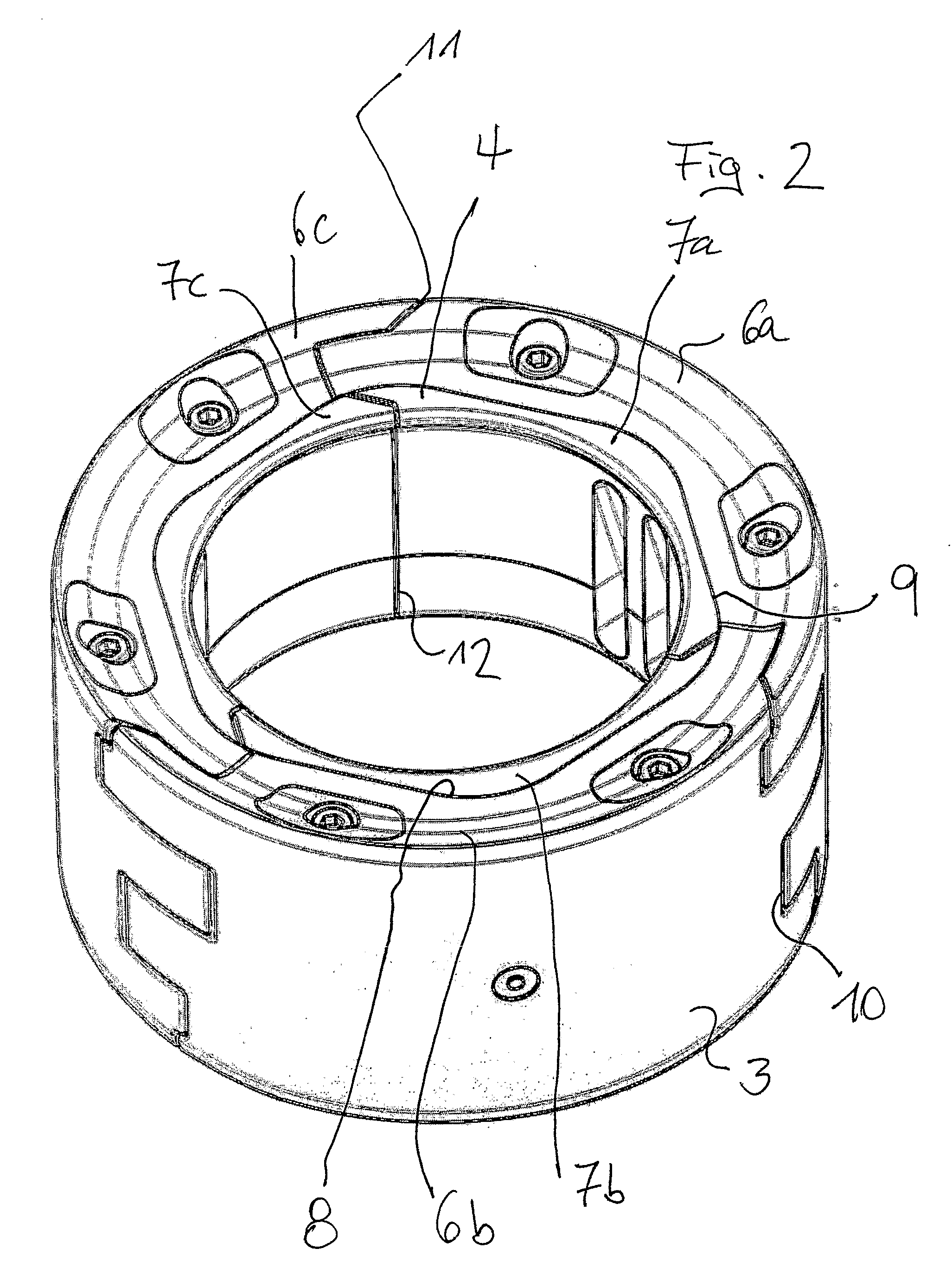
[0032] The bond of upper (radially outer) shell 3 and lower (radially inner) shell 4 is shown in more detail in a perspective view in FIG. 2. The upper shell 3 comprises three segments 6a, 6b and 6c; the lower shell 4 is likewise composed of three segments 7a, 7b and 7c. The segments 6a through 6c of the upper shell 3 are connected by a positive connection to the segments 7a through 7c of the lower shell 4 in that the radially inner contour 8 of the upper shell 3 and the radially outer contour 9 of the lower shell 4 have the shape of a polygon. The segments 6a and 6b of the upper shell 3 have a toothing 10 that...


PUM


Abstract

A vehicle wheel with a wheel rim and a solid tire positioned on the wheel rim. The vehicle wheel has an annular upper shell having a first wedge-shaped surface and composed of at least two upper segments. Further, the vehicle wheel includes an annular lower shell composed of lower segments and having an outer circumference having a second wedge-shaped surface. Moreover, the second wedge-shaped surface is structured and arranged in a diametrically opposed manner to the first wedge-shaped surface. Additionally, the annular lower shell is arranged on the rim, the annular lower shell is arranged against the annular upper shell, and the annular upper shell is connected to the solid tire.

Description

CROSS REFERENCE TO RELATED APPLICATIONS [0001] The present application is a U.S. National Stage Application of International Application No. PCT / EP2004 / 010927 filed Sep. 30, 2004, which published as WO 2006 / 037353 A1 Apr. 13, 2006, the disclosure of which is expressly incorporated by reference herein in its entirety.BACKGROUND OF THE INVENTION [0002] 1. Field of the Invention [0003] The invention relates to a vehicle wheel with a wheel rim and a solid tire positioned on the wheel rim. The wheel rim includes an annular lower shell composed of segments and having a wedge-shaped surface on an outer circumference braced against a wedge-shaped surface of an annular upper shell embodied in a diametrically opposed manner to the wedge-shaped surface of the lower shell. The lower shell is arranged on the wheel rim and the upper shell is connected to the solid tire. [0004] 2. Description of Background Information [0005] A vehicle wheel of this type is known from EP 1 312 489 A2. The essential...

Claims


Application Information

Patent Timeline
Patent Type & Authority Applications(United States)
IPC IPC(8): B60C19/00
CPCB60C7/24B60C7/22B60C7/00B60B5/02B60B25/02B60B25/22
Inventor SAUERWALD, JUERGEN H.SCHOLZ, KLAUS
Owner CONTINENTAL REIFEN DEUTSCHLAND GMBH
Learn More