
Atomic oscillator, method for sealing temperature detecting means, and rubidium atomic oscillator

a technology of atomic oscillators and temperature sensors, which is applied in the direction of electrical heating, automatic control, electrical equipment, etc., can solve the problems of disadvantageous inability to check with eyes from the opening side, the complexity of the temperature sensor, and the increase in cost etc., to achieve the effect of simplifying the structure improving the sensitivity of the temperature sensor, and realizing the cost effectively

Inactive Publication Date: 2007-10-18
SEIKO EPSON CORP
View PDF4 Cites 13 Cited by
  • Summary
  • Abstract
  • Description
  • Claims
  • Application Information

AI Technical Summary

Benefits of technology

[0009]An advantage of the present invention is to provide a method for sealing a temperature detecting means. In the method, a temperature sensor is structured to be simple and not to be exposed to air, improving temperature detection sensitivity thereof.
[0010]In addition, another advantage of the present invention is to provide a temperature sensor realized inexpensively by simplifying the structure thereof and made available without limiting its installation sites.
[0011]An atomic oscillator according to an aspect of the invention includes: a gas cell encapsulating a rubidium atom; a gas cell holding member holding the gas cell; a rubidium lamp exciting the rubidium atom in the gas cell; a lamp holding member holding the rubidium lamp; a temperature detecting means disposed in a recessed part provided to at least one of the gas cell holding member and the lamp holding member; and grease closely contacting an exterior surface of the temperature detecting means disposed in the recessed part and burying the temperature detecting means therein.
[0012]The gas cell encapsulating the rubidium atom and the rubidium lamp need to be maintained at constant temperature so as to stabilize an excitation of rubidium gas. Therefore, a thermal cylinder (holding member) holding each of the gas cell and the rubidium lamp is provided, and to the thermal cylinder, a heater heating the thermal cylinder and a temperature sensor (temperature detecting means) detecting a temperature of the thermal cylinder are provided. At this time, the aspect fills the recessed part provided to part of each holding member with the grease having good fluidity and buries a sensor detecting the temperature of the each holding member in the grease. This can increase the temperature detection sensitivity considerably and prevent generation of the air bubble (vacancy) at the periphery of the temperature sensor.
[0014]In order to detect the temperature of the thermal cylinder with good responsiveness, it is important to conduct the heat of the thermal cylinder to the sensor as fast as possible. Therefore, the grease closely contacting the temperature sensor needs to have high thermal conductivity. Using high thermal conductive silicon grease having good fluidity can increase the thermal conductivity.

Problems solved by technology

However, the conventional method for fixing the temperature sensor with silicon rubber has problems as below.
In addition, since the silicon rubber 40 becomes clouded to lose its transparency when hardening, the state of the temperature sensor 35 in the recessed part 44 disadvantageously can not be checked with eyes from the opening side.
Further, the conventional art of the above example has such problems that the temperature sensor has a complex structure to increase in cost and the shape thereof is predetermined to limit its installation sites.

Method used


Image

  • Atomic oscillator, method for sealing temperature detecting means, and rubidium atomic oscillator
  • Atomic oscillator, method for sealing temperature detecting means, and rubidium atomic oscillator
  • Atomic oscillator, method for sealing temperature detecting means, and rubidium atomic oscillator

Examples


first embodiment

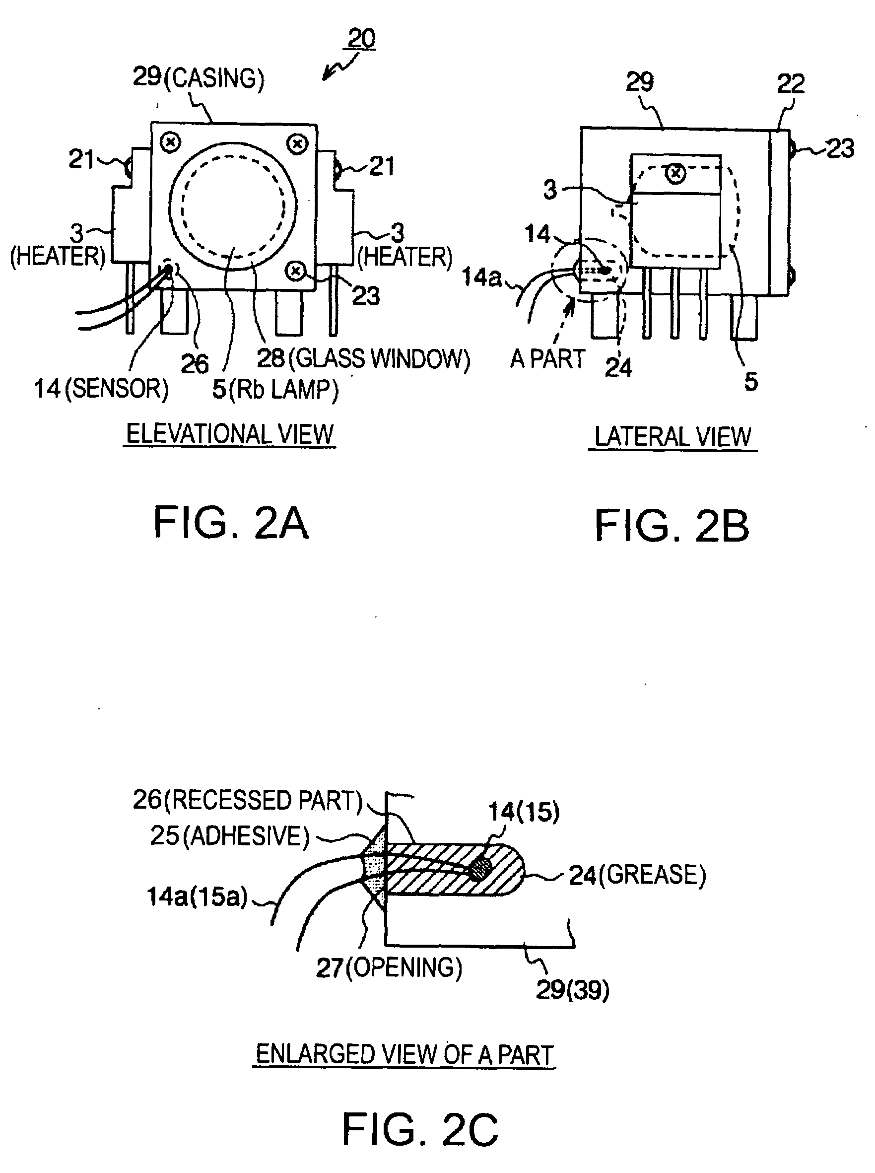
[0044]FIGS. 2A to 2C are schematic views showing a lamp thermal cylinder according to a first embodiment of the invention. Elements same as the ones in FIG. 1 are given the same reference numbers to be explained. FIG. 2A is an elevational view, FIG. 2B is a lateral view, and FIG. 2C is an enlarged view of A part of FIG. 2B. This lamp thermal cylinder 20 is provided with a casing 29 made of metal and having a cylindrical structure so as to house the Rb lamp 5 therein; a recessed part 26 provided on part of the surface of the casing 29; the temperature sensor 14 disposed in the recessed part 26; and grease 24 filling the recessed part 26 so as to cover and bury the temperature sensor 14. The recessed part 26 is formed in a bag shape from an opening 27 provided on the surface of the casing 29 toward the inside of the casing 29.

[0045]Further, on the elevational face of the casing 29, a lid 22 protecting the Rb lamp 5 is fixed by a screw 23, and to the lid 22, a glass window 28 for extra...

second embodiment

[0059]FIG. 4 is a schematic view showing a recessed part sealed with a sealing member according to a second embodiment of the invention. Elements same as the ones in FIG. 2C are given the same reference numbers to be explained. The sealing member prevents the grease 24 from leaking to the outside. Therefore, a lid member 36 fitting the opening 27 of the recessed part 26 may be prepared so as to seal the grease 24 filling the recessed part 26. In the case, the lid member 36 is preferably made of high thermal conductive material. In addition, the gas cell thermal cylinder 30 reaches extremely high temperature. Therefore, the lid member 36 sealing the grease 24 needs to have at least thermal resistance so as not to transform or melt due to the heat.

[0060]FIG. 5 is a schematic diagram showing a common concept of negative feedback. Note that each element has a different reference number from the one in the above embodiments. A thermostat part of a rubidium atomic oscillator of the invent...


PUM


Abstract

An atomic oscillator includes: a gas cell encapsulating a rubidium atom; a gas cell holding member holding the gas cell; a rubidium lamp exciting the rubidium atom in the gas cell; a lamp holding member holding the rubidium lamp; a temperature detecting means disposed in a recessed part provided to at least one of the gas cell holding member and the lamp holding member; and grease closely contacting an exterior surface of the temperature detecting means disposed in the recessed part and burying the temperature detecting means therein.

Description

BACKGROUND[0001]1. Technical Field[0002]The present invention relates to an atomic oscillator, a method for sealing a temperature detecting means, and a rubidium atomic oscillator. More particularly, the invention relates to a method for sealing a temperature detecting means provided to a thermostat part of a rubidium atomic oscillator.[0003]2. Related Art[0004]A method shown in FIG. 5, for example, is known as a conventional method for controlling a temperature of thermal cylinders (holding members) holding a rubidium gas cell and a rubidium lamp respectively in an atomic oscillator of a rubidium gas cell system. The method detects heat 38 from a heater 34 by a temperature sensor 35 and negatively feeds a temperature data from the temperature sensor 35 back through an amplifier 37 to maintain the heater 34 at constant temperature. In the conventional art, as shown in FIGS. 6A to 6C, the temperature sensor 35 is inserted into a recessed part 44 having a predetermined depth and provi...

Claims


Application Information

Patent Timeline
IPC IPC(8): H05B1/02
CPCH03L7/26G04F5/14
Inventor SHIBATA, TSUNENORICHINDO, KOJI
Owner SEIKO EPSON CORP
Learn More