High frequency multilayer bandpass filter

a bandpass filter and high-frequency technology, applied in waveguides, waveguide type devices, electrical equipment, etc., can solve the problems of increasing the thickness difficult to produce a low-loss bandpass filter with desired characteristics, and increasing the insertion loss of the multi-layer bandpass filter, so as to achieve low ripple in the passband and reduce the effect of insertion loss

Active Publication Date: 2007-10-18
MURATA MFG CO LTD
View PDF11 Cites 154 Cited by
  • Summary
  • Abstract
  • Description
  • Claims
  • Application Information

AI Technical Summary

Benefits of technology

[0016] To overcome the problems described above, preferred embodiments of the present invention provide a small-sized

Problems solved by technology

Furthermore, the two-layer coil pattern causes a reduction in the Q value of the coil, which results in an increase in insertion loss of the multilayer bandpass filter.
However, this results in an increase in the thickness of the multilayer bandpass filter.
However, i

Method used


Image

  • High frequency multilayer bandpass filter
  • High frequency multilayer bandpass filter
  • High frequency multilayer bandpass filter

Examples


first preferred embodiment

[0129] A multilayer bandpass filter according to a first preferred embodiment is described below with reference to FIGS. 2A to 9B.

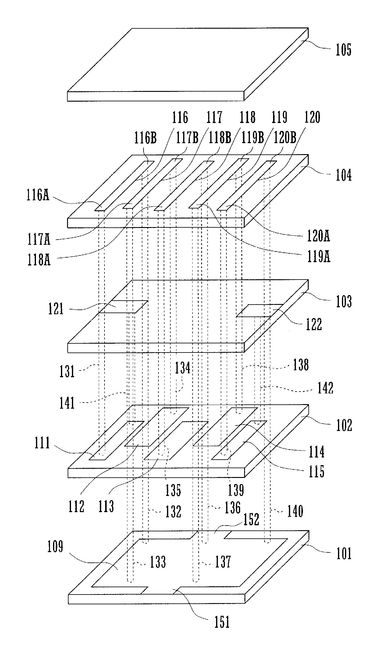
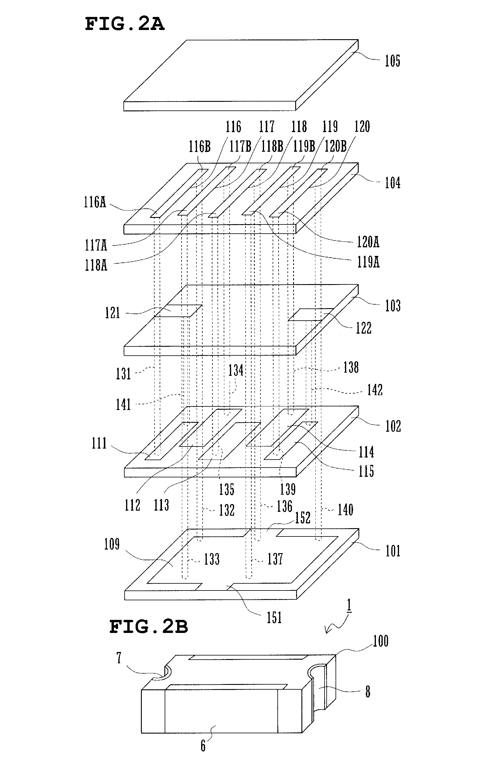
[0130]FIG. 2A shows an exploded perspective view of a multilayer bandpass filter according to a first preferred embodiment, and FIG. 2B is a perspective view showing an appearance of the multilayer bandpass filter.

[0131] As shown in FIG. 2A, the multilayer bandpass filter includes a ground electrode formation layer 101, a capacitor electrode formation layer 102, an input / output electrode formation layer 103, a line electrode formation layer 104, and an external layer 105. In each of these layers, a particular electrode pattern is provided on the upper surface of a dielectric layer, and these layers are disposed on one another in a multilayer structure.

[0132] As shown in FIG. 2A, a ground electrode 109 is provided on the upper surface of the ground electrode formation layer 101. Capacitor electrodes 111 to 115 are provided in the capacitor electrode for...

second preferred embodiment

[0150]FIG. 4 is an exploded perspective view of a multilayer bandpass filter according to a second preferred embodiment of the present invention. FIG. 4 is represented in a similar manner to FIG. 2A for convenience of comparison therewith. In FIG. 4, similar parts to those in FIG. 2A are denoted by similar reference numerals.

[0151] The multilayer bandpass filter according to the second preferred embodiment is different from that according to the first preferred embodiment in the manner of extending input / output electrodes and the polarity of inductive coupling between adjacent LC parallel resonators.

[0152] The multilayer bandpass filter according to this second preferred embodiment is in the form of a multilayer structure including a ground electrode formation layer 101, a capacitor electrode formation layer 202, a line electrode formation layer 104, and an external layer 105.

[0153] A ground electrode 109 and ground connection electrodes 151 and 152 are provided in the ground ele...

third preferred embodiment

[0158] A multilayer bandpass filter according to a third preferred embodiment of the present invention is described below with reference to FIGS. 5 to 9B.

[0159] In this third preferred embodiment, the multilayer bandpass filter includes three LC parallel resonators, and its equivalent circuit is represented as shown in FIG. 5. In the first and second preferred embodiments described above, five (five stages of) LC parallel resonators are coupled. In the third preferred embodiment, each inductor electrode includes two via-electrodes and one line electrode.

[0160]FIGS. 6A to 9B show dependence of the characteristics of the three-stage multilayer bandpass filter configured in the above-described manner on polarities of inductive coupling between adjacent LC parallel resonators, that is, on the loop directions of the inductor electrodes. That is, FIGS. 6A to 9B show transfer characteristics (S21 of S parameters) for respective configurations in terms of the coupling polarity, wherein FI...


PUM


Abstract

In a multilayer bandpass filter, capacitances are produced between a ground electrode provided in a ground electrode formation layer and capacitor electrodes provided in a capacitor electrode formation layer. A plurality of inductor electrodes are defined by via-electrodes and line electrodes such that loop planes of inductor electrodes at least partially overlap each other when seen in a direction in which the inductor electrodes are arranged. The direction of the loop of the inductor electrode of the LC parallel resonator located (at a first stage) at an input end is set to be opposite to the direction of the loop of the inductor electrodes of the LC parallel resonator (at a second stage) adjacent to the inductor electrode of the LC parallel resonator located at the input end. Similarly, the direction of the loop of the inductor electrode of the LC parallel resonator located (at a fifth stage) at an output end is set to be opposite to the direction of the loop of the inductor electrodes of the LC parallel resonator (at a fourth stage) adjacent to the inductor electrode of the LC parallel resonator located at the output end.

Description

BACKGROUND OF THE INVENTION [0001] 1. Field of the Invention [0002] The present invention relates to a multilayer bandpass filter having a multilayer structure including a plurality of dielectric layers and a plurality of electrode layers. [0003] 2. Description of the Related Art [0004] It is known to manufacture a small-sized low-cost high-frequency bandpass filter by producing a plurality of LC resonators in a multilayer structure including dielectric layers and electrode layers. [0005] Examples of such multilayer bandpass filters are disclosed in Japanese Unexamined Patent Application Publication No. 4-6911 (Patent Document 1), Japanese Unexamined Patent Application Publication No. 2000-201001 (Patent Document 2), Japanese Unexamined Patent Application Publication No. 2003-198226 (Patent Document 3), and International Publication Pamphlet No. 02 / 009225 (Patent Document 4). [0006] Referring to FIGS. 1A and 1B, a multilayer bandpass filter disclosed in Patent Document 1 is describe...

Claims


Application Information

Patent Timeline
IPC IPC(8): H03H7/01
CPCH03H7/09H03H7/1708H03H2001/0085H03H7/1775H03H7/1791H03H7/1725
Inventor TANIGUCHI, TETSUO
Owner MURATA MFG CO LTD
Why Eureka
Try Eureka