Elastic wave filter including a grating reflector between tapered input and output IDT electrodes

a technology of grating reflector and idt electrode, which is applied in piezoelectric/electrostrictive/magnetostrictive devices, piezoelectric/electrostriction/magnetostriction machines, electrical equipment, etc., can solve the problems of deterioration of attenuation characteristics, high frequency side deterioration, and need for improvement, so as to improve filter selectivity and increase the effect of attenuation in the stop band

Inactive Publication Date: 2012-06-26
NIHON DEMPA KOGYO CO LTD
View PDF10 Cites 3 Cited by
  • Summary
  • Abstract
  • Description
  • Claims
  • Application Information

AI Technical Summary

Benefits of technology

[0016]The present invention is made in view of such circumstances, and an object thereof is to provide an elastic wave filter capable of obtaining steep attenuation at a high band side or a low band side in a pass band and having high selectivity.
[0024]According to the elastic wave filter of the present invention, the width dimension of the electrode finger and the distance dimension between the electrode fingers in the grating reflector provided between the input side tapered IDT electrode and the output side tapered IDT electrode are constituted to be equal to or less than the minimum value of the width dimension of the electrode finger and the distance dimension between the electrode fingers in the IDT electrodes, or to be equal to or more than the maximum value thereof. Thus, attenuation in a stop band can be increased, and it is possible to obtain steep attenuation at the high band side or the low band side, and improve filter selectivity by matching the attenuation with a vicinity of the high band side or the low band side in the pass band.

Problems solved by technology

In the above SAW filter 100 particularly, there exists a problem that an attenuation characteristic at a high frequency side (high band side) deteriorates compared with that at a low frequency side (low band side), and therefore, improvement thereof has been required.
Due to the energy loss, the deterioration of the attenuation characteristic is caused at both the high band side and the low band side.
When the propagation distance L becomes long as described above, the energy loss caused by the refraction is likely to occur.
However, Patent Document 1 and Patent Document 2 do not disclose the above-described problems, and accordingly, these problems cannot be solved.[Patent Document 1] Japanese Patent Application Laid-open No.

Method used


Image

  • Elastic wave filter including a grating reflector between tapered input and output IDT electrodes
  • Elastic wave filter including a grating reflector between tapered input and output IDT electrodes
  • Elastic wave filter including a grating reflector between tapered input and output IDT electrodes

Examples


first embodiment

[0043](First Embodiment)

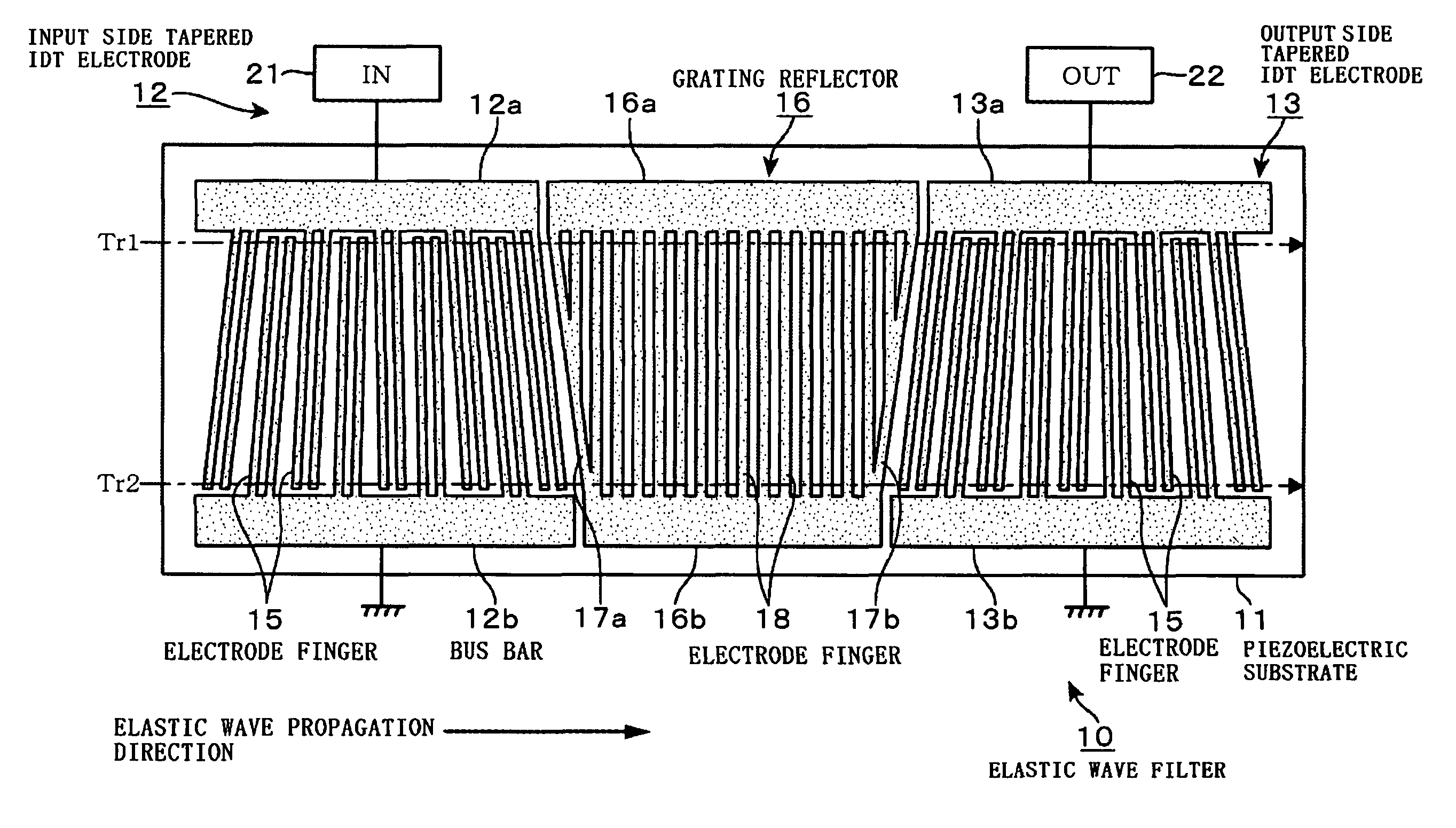
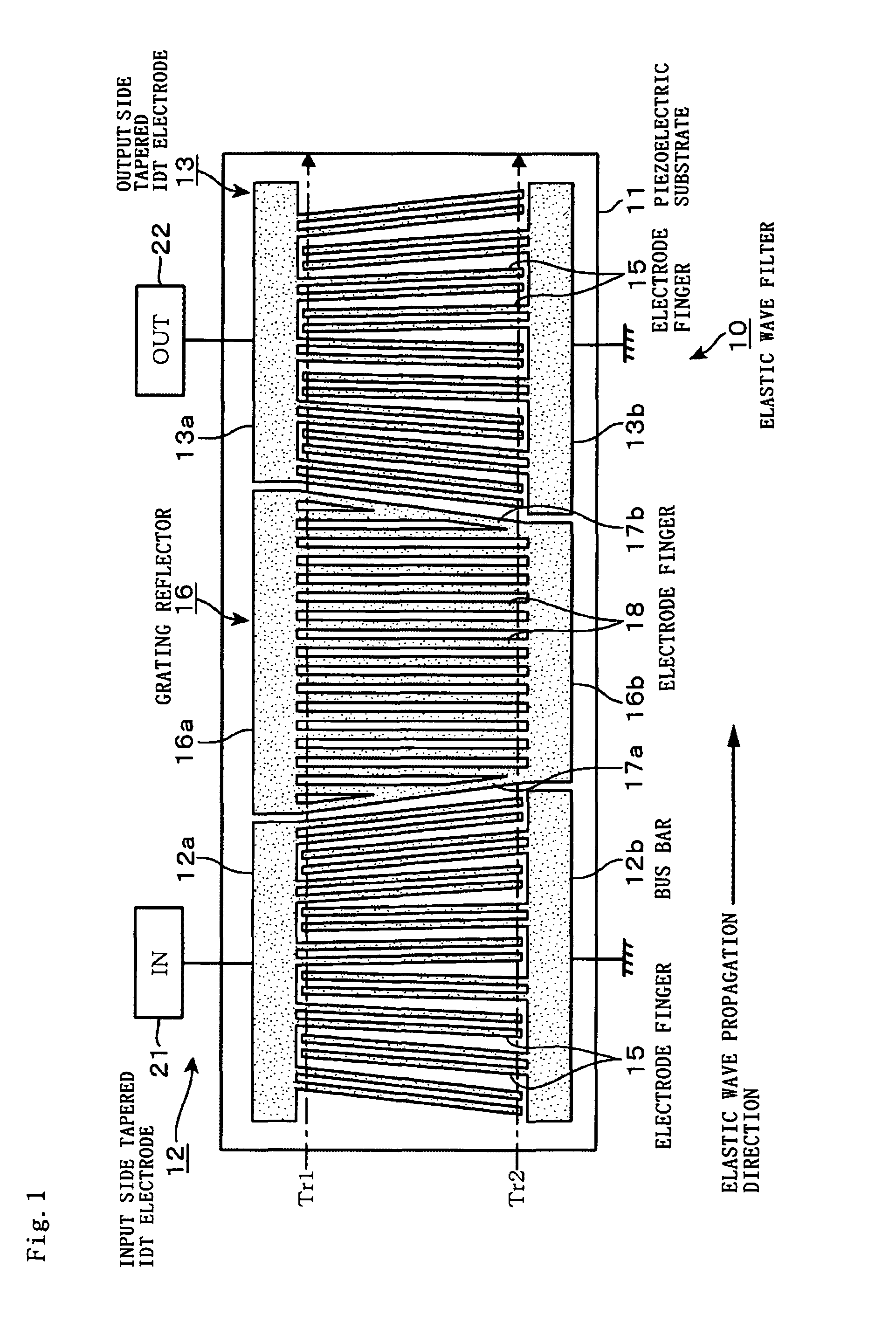
[0044]An elastic wave filter 10 being a first embodiment of the present invention will be explained with reference to FIG. 1 and FIG. 2. The elastic wave filter 10 is designed to make attenuation at a high band side in a pass band steep, and there are formed an input side tapered IDT electrode 12 and an output side tapered IDT electrode 13 having the same configuration as those of the input side tapered IDT electrode 102 and the output side tapered IDT electrode 103 in the filter 100 shown in the drawing, which are already described, on a surface of a piezoelectric substrate 11. The input side tapered IDT electrode 12 and the output side tapered IDT electrode 13 are provided apart from each other in a propagation direction of an elastic wave. Note that in order to distinguish among a piezoelectric substrate, electrodes, and a reflector, the respective drawings showing the filter configuration are shown with a large number of dots added to the electrodes and t...

second embodiment

[0064](Second Embodiment)

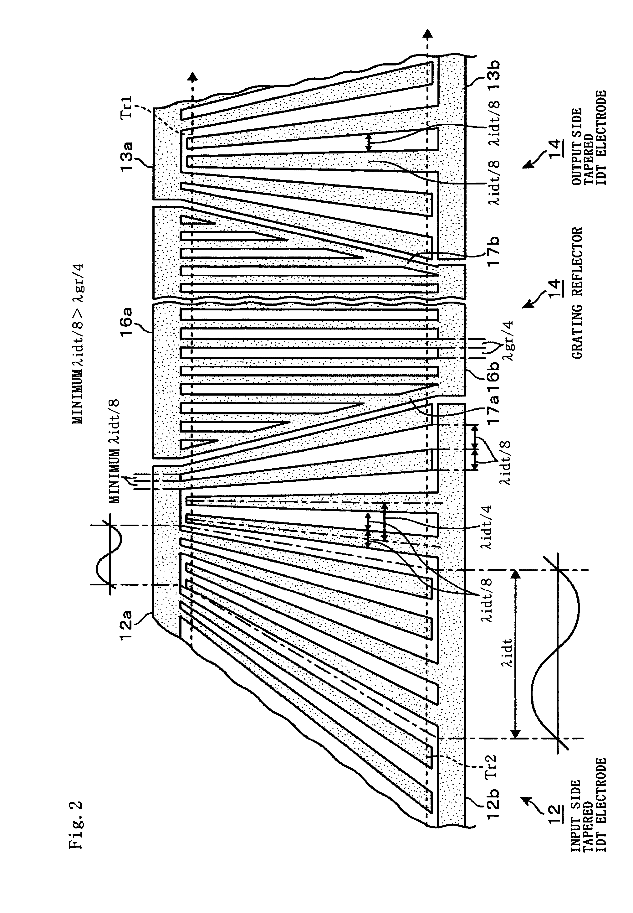
[0065]Subsequently, an elastic wave filter 30 in a second embodiment will be explained with reference to FIG. 5 and FIG. 6. The elastic wave filter 30 is designed to make attenuation at a low band side in a pass band thereof steep, and hereinafter, points different from the configuration of the elastic wave filter 10 will be mainly explained. A grating reflector 16 in the elastic wave filter 30 is provided with a large number of electrode fingers 31 in place of a large number of the electrode fingers 18. The electrode fingers 31 are formed to have equal widths, and extend from a bus bar 16a to a bus bar 16b, and are arranged at equal distances from an input side to an output side repeatedly. Then, λgr / 4 being a width dimension of the electrode finger 31 and a distance dimension (pitch) between the adjacent electrode fingers 31, 31 is formed slightly larger than a maximum λidt / 8 being a width dimension of an electrode finger 15 and a distance dimension betwee...

third embodiment

[0069](Third Embodiment)

[0070]Subsequently, an elastic wave filter 40 in a third embodiment will be explained with reference to FIG. 8 and FIG. 9. The elastic wave filter 40 is designed to make attenuation in a stop band at a high band side in a pass band thereof steep similarly to the elastic wave filter 10 in the first embodiment, and is further configured to attenuate frequency signals in a range wider than that of the elastic wave filter 10 in the stop band. Hereinafter, points different from the configuration of the elastic wave filter 10 will be mainly explained. In a grating reflector 16 in the elastic wave filter 40, an arrangement pattern of electrode fingers 41 provided in place of the already-described electrode fingers 18 is formed so that a distance between the adjacent electrode fingers 41, 41 is gradually widened from an upper side toward a lower side in the drawing, namely in a direction perpendicular to a propagation direction of an elastic wave, and further each wi...


PUM


Abstract

To provide an elastic wave filter capable of obtaining steep attenuation at a high band side or a low band side in a pass band and having high selectivity. An elastic wave filter is configured in a manner that when seen in a propagation direction of an elastic wave, as for respective electrode fingers composing each group of electrode fingers in an input side tapered IDT electrode and an output side tapered IDT electrode, width dimensions thereof are the same one another, and a distance dimension between the adjacent electrode fingers is formed to be the same as the width dimension of the electrode finger, when seen in the propagation direction of an elastic wave, as for a group of electrode fingers in a grating reflector, width dimensions of respective electrode fingers composing the group of the electrode fingers are the same, and a distance dimension between the adjacent electrode fingers is formed to be the same as the width dimension, and the width dimension of the electrode finger and the distance dimension between the electrode fingers are set to be equal to or less than a minimum value or equal to or more than a maximum value of the width dimension of the electrode finger and the distance dimension between the electrode fingers in the input side tapered IDT electrode and the output side tapered IDT electrode.

Description

BACKGROUND OF THE INVENTION[0001]1. Field of the Invention[0002]The present invention relates to an elastic wave filter, for example, an (SAW: Surface Acoustic Wave) filter.[0003]2. Description of the Related Art[0004]A SAW device makes good use of surface acoustic waves and by disposing electrode fingers called an IDT (interdigital transducer) on a piezoelectric substrate, and performing an electromechanical interconversion between an electrical signal and an elastic wave, to have frequency selection (band filter) characteristics. The SAW filter, one of the SAW devices, is used as a band pass filter for various communication devices such as a cellular phone, in which sophistication in performance and miniaturization have been proceeding. In recent years, with advances in speeding up and enlarging capacity of wireless data communication, demands for a smaller insertion loss (attenuation of output power to input power), excellent filter characteristics in frequency selectivity, a wid...

Claims


Application Information

Patent Timeline
Patent Type & Authority Patents(United States)
IPC IPC(8): H03H9/64
CPCH03H9/02716H03H9/14547H03H9/14558H03H9/14561H03H9/14564H03H9/14567H03H9/643H03H9/6493
Inventor TSUDA, TADAAKI
Owner NIHON DEMPA KOGYO CO LTD
Why Eureka
Try Eureka