Laminated band pass filter

a technology of laminated band and filter, applied in the direction of impedence networks, multiple-port networks, electrical equipment, etc., can solve the problems of large insertion loss large thickness and the size of laminated band pass filters, and difficulty in configuring resonators, etc., to achieve steep attenuation and reduce ripple in the band

Active Publication Date: 2012-07-03
MURATA MFG CO LTD
View PDF25 Cites 5 Cited by
  • Summary
  • Abstract
  • Description
  • Claims
  • Application Information

AI Technical Summary

Benefits of technology

[0017]Accordingly, preferred embodiments of the present invention solve the above problems and provide a laminated band pass filter which attains steep attenuation from a pass band to an out-of pass band and reduced ripple in the band.

Problems solved by technology

Furthermore, since the coils are formed in the two-layer coil pattern, there arises a problem in that insertion loss of the laminated band pass filter becomes large due to deterioration of Q values of the coils.
However, in this case, the thickness and the size of the laminated band pass filter become large.
In this case, it is difficult to configure a resonator having a desired inductance, and there arises a problem in that a low-loss characteristic of the band pass filter is not obtained.
Therefore, there arises a problem in that, when a filter having multiple stages is configured, the thickness thereof becomes large.

Method used


Image

  • Laminated band pass filter
  • Laminated band pass filter
  • Laminated band pass filter

Examples


Embodiment Construction

[0045]A laminated band pass filter according to preferred embodiments will be described hereinafter. The filter described hereinafter is a band pass filter in which LC parallel resonators in three layers are connected to one another.

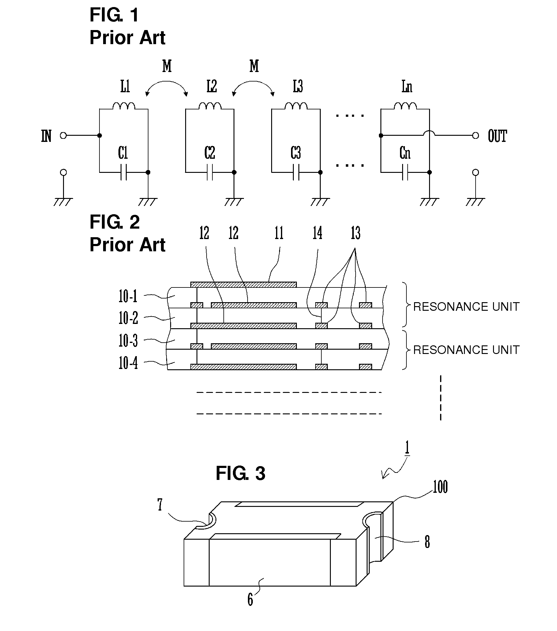
[0046]FIG. 3 is a perspective view of appearance of the band pass filter.

[0047]A laminated band pass filter 1 includes a laminated body 100. The laminated body 100 is configured such that dielectric layers and electrode layers are laminated on one another in a vertical direction serving as a lamination direction. Among four sides which are parallel to the lamination direction of the laminated body 100, on two sides having short sides, input / output terminals 7 and 8 are arranged, and on the remaining other two sides, ground terminals 6 are arranged. The presence of the ground terminals 6 between the input / output terminals 7 and 8 prevents input / output signals from being unnecessary coupled.

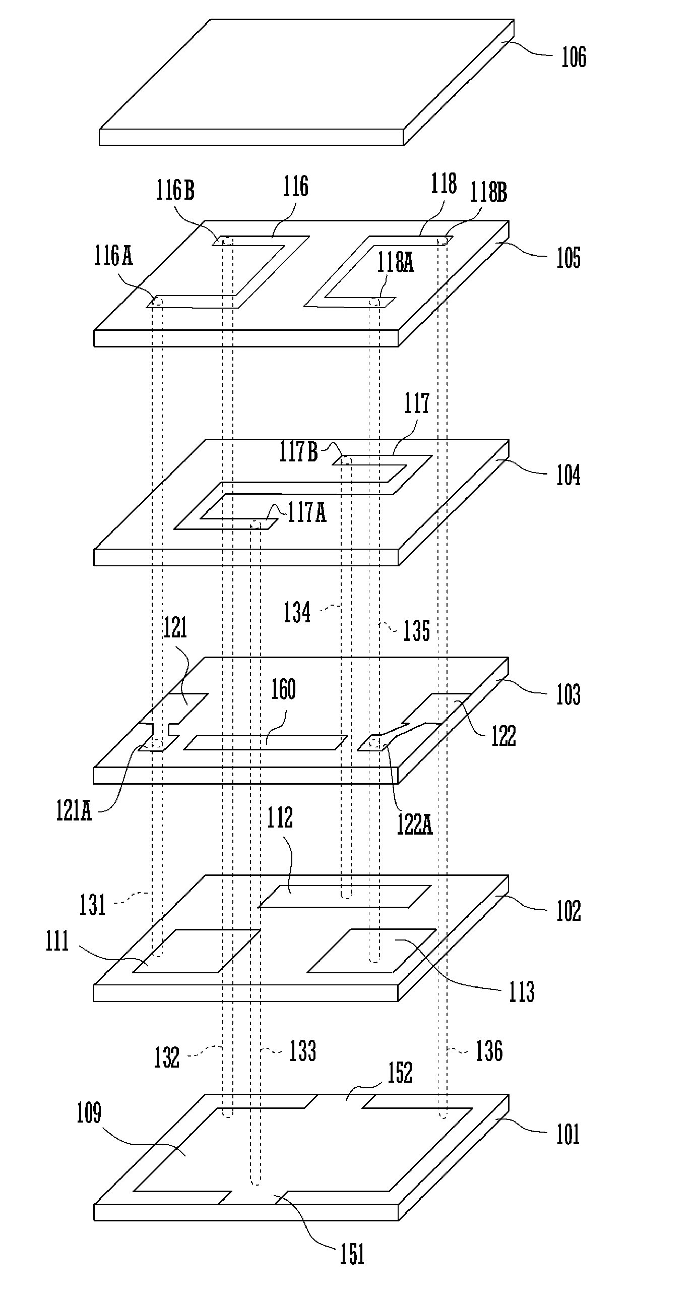
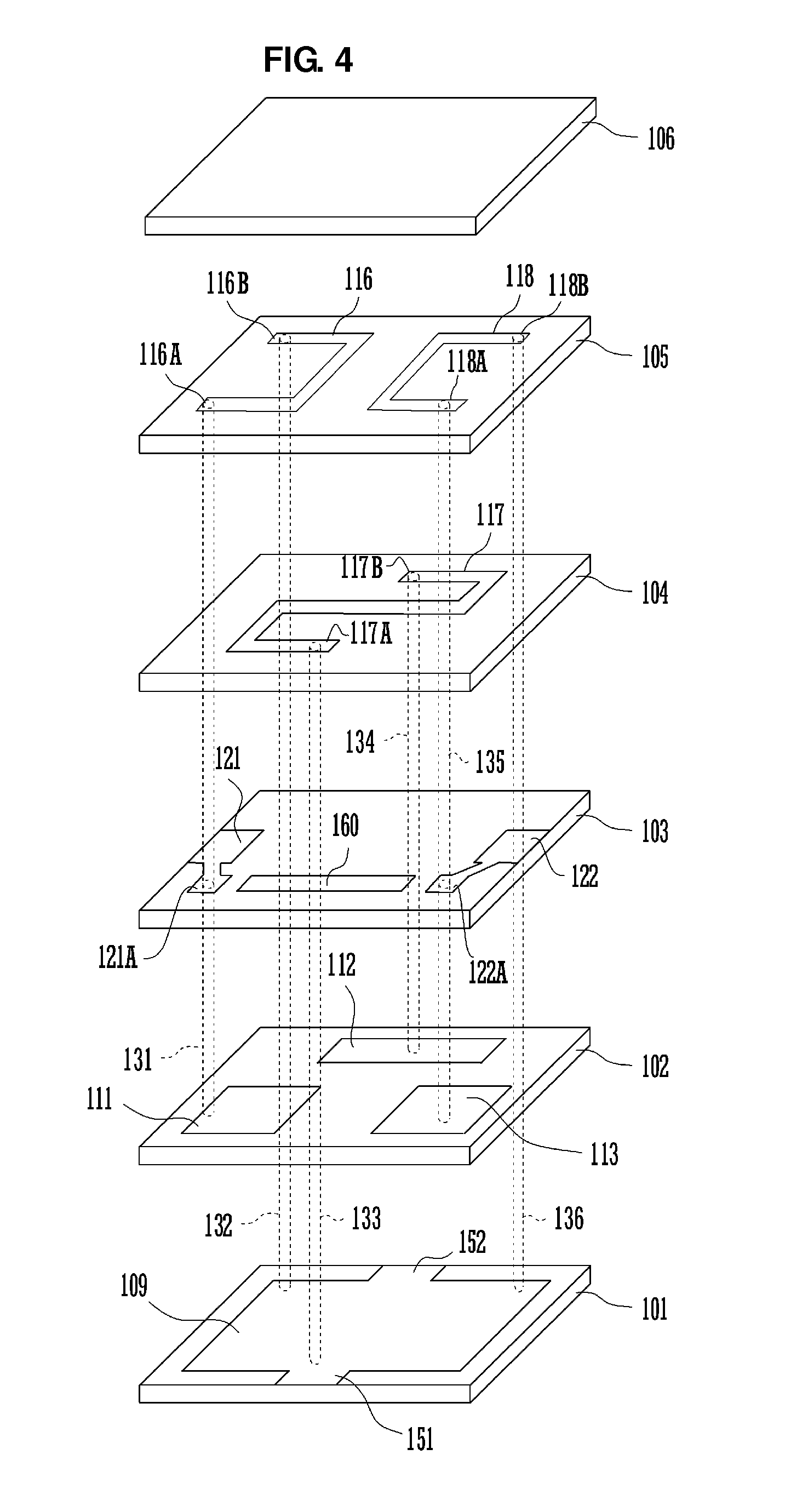
[0048]FIG. 4 is an exploded perspective view illustrating the filt...


PUM


Abstract

A small low-loss laminated band pass filter attains steep attenuation from a pass band to out-of pass band and reduced ripple in the band. Capacitances are generated between a ground electrode on a ground electrode forming layer and capacitor electrodes on a capacitor electrode forming layer, a plurality of inductor electrodes are defined by via electrodes and the line electrodes, and portions of respective loop surfaces of the inductor electrodes overlap with one another when viewed from a direction of arrangement of the inductor electrodes. Furthermore, a line electrode is arranged on a first line electrode forming layer and line electrodes are arranged on a second line electrode forming layer.

Description

BACKGROUND OF THE INVENTION[0001]1. Field of the Invention[0002]The present invention relates to a laminated band pass filter including a plurality of dielectric layers and a plurality of electrode layers laminated on one another.[0003]2. Description of the Related Art[0004]In general, a laminated band pass filter is used as a high-frequency band pass filter. The laminated band pass filter is configured such that a plurality of LC resonators are included in a laminated body constituted by laminating dielectric layers and electrode layers. The laminated band pass filter thus configured is suitable for miniaturization and cost reduction.[0005]Conventional laminated band pass filters are disclosed in Japanese Unexamined Patent Application Publication No. 4-6911, Japanese Unexamined Patent Application Publication No. 2000-201001, Japanese Unexamined Patent Application Publication No. 2003-198226, and International Publication No. 02 / 009225.[0006]FIG. 1 is a circuit diagram illustrating ...

Claims


Application Information

Patent Timeline
Patent Type & Authority Patents(United States)
IPC IPC(8): H03H7/09
CPCH03H7/0115H03H7/09H03H7/1708H03H7/1775H03H2001/0085
Inventor TANIGUCHI, TETSUO
Owner MURATA MFG CO LTD
Why Eureka
Try Eureka