
Tire information detecting system

Inactive Publication Date: 2007-10-18
ALPS ALPINE CO LTD
View PDF3 Cites 4 Cited by
  • Summary
  • Abstract
  • Description
  • Claims
  • Application Information

AI Technical Summary

Benefits of technology

[0013]Accordingly, it is an object of the present invention to provide a tire information detecting system that can reduce the affects of external factors and accurately detect the desired tire information, such as a tire pressure.

Problems solved by technology

However, in the above-described wireless transmission systems, the resonance frequency of the resonator in the transponder is affected by not only the desired tire information such as a tire pressure but also other factors, such as temperature.
Thus, an error occurs in the measured value due to a change in temperature in the tire, and therefore, the measured value is not accurate.
In addition, even when the transponder further includes a reference resonator to compute the measured value of a tire pressure, an error in the measured value still occurs, since the temperature characteristics and the secular change characteristics of the quartz crystal resonating elements of the resonators are different.
Accordingly, an accurate measured value cannot be obtained.

Method used


Image

  • Tire information detecting system
  • Tire information detecting system
  • Tire information detecting system

Examples


Embodiment Construction

[0027]An embodiment of the present invention is now herein described in detail with reference to the accompanying drawings. According to the present embodiment, like the above-described known tire information detecting system (wireless transmission system), a tire information detecting system includes a controller disposed on the body of a vehicle and a measured value transmitter (hereinafter referred to as a “transponder”) disposed in a tire.

[0028]In particular, the configuration of the transponder of the tire information detecting system according to the present embodiment is different from that of the known tire information detecting system. The circuit configuration of the transponder of the tire information detecting system according to the present embodiment is described below. The difference between the configurations of the controllers is described with reference to components shown in FIG. 5 as needed.

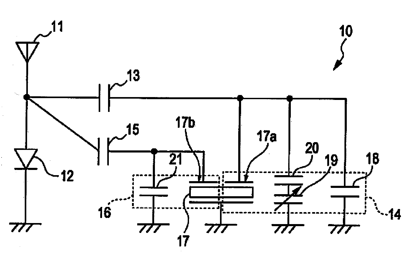
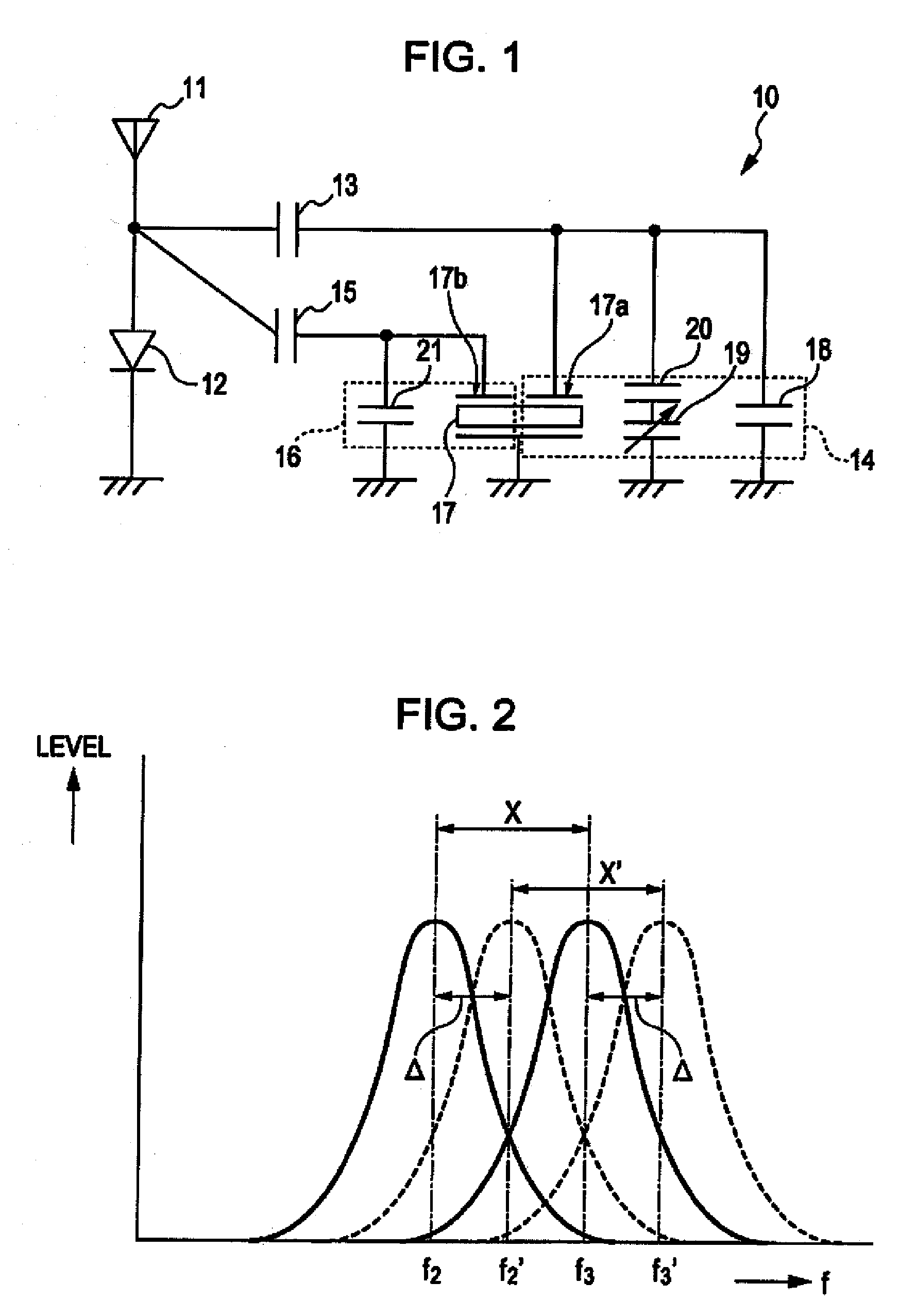
[0029]FIG. 1 illustrates an exemplary circuit configuration of the transp...


PUM


Abstract

A transponder includes an antenna, a modulation / demodulation unit (diode) that modulates and demodulates signals received and transmitted from and to a controller, a pressure resonator including a first piezoelectric single-crystal resonating element and a pressure sensor. The resonance frequency of the pressure resonator changes in accordance with a change in tire pressure, and a reference resonator includes a second piezoelectric single-crystal resonating element and a capacitor, where the resonance frequency of the reference resonator is unaffected by the change in tire pressure. The first and second piezoelectric single-crystal resonating elements are integrally formed on a single-crystal piece. The controller transmits a signal for resonating the pressure resonator and the reference resonator, receives signals modulated with the resonance frequencies of the pressure resonator and the reference resonator, and computes a measured value in accordance with the resonance frequencies of the two resonators retrieved from the received signals.

Description

[0001]This application claims the benefit of priority under 35 U.S.C. § 119 to Japanese Patent Application No. 2006-097771 filed Mar. 31, 2006, and is hereby incorporated by reference in its entirety.BACKGROUND OF THE INVENTION[0002]1. Field of the Invention[0003]The present invention generally relates to a tire information detecting system. In particular, the invention relates to a tire information detecting system used for motor vehicles to detect tire information, such as a tire pressure.[0004]2. Description of the Related Art[0005]Wireless transmission systems have been developed that wirelessly transmit a measured value, such as tire pressure of a motor vehicle or the like, to a controller disposed on the body of the motor vehicle to evaluate that value and determine whether to output a warning message to a driver (refer to, for example, Japanese Patent No. 3494440 and, in particular, FIGS. 3 and 5). Such wireless transmission systems include a controller (as shown in FIG. 5) d...

Claims


Application Information

Patent Timeline
IPC IPC(8): B60C23/02B60C23/00
CPCB60C23/0449
Inventor MASUDAYA, HIDEKI
Owner ALPS ALPINE CO LTD
Learn More