
Image display apparatus

a technology of image display and display screen, which is applied in the field of image display screen, can solve the problems of inability to appropriately restore (or conceal) the macroblocks of the image frame, the inability to handle such frame loss, and the inability to completely discard the entire image frame or lose it, so as to prevent the disturbance and interruption of the image display and achieve high-quality images

Active Publication Date: 2007-10-18
MAXELL HLDG LTD
View PDF15 Cites 54 Cited by
  • Summary
  • Abstract
  • Description
  • Claims
  • Application Information

AI Technical Summary

Benefits of technology

[0009]The present invention has been devised in view of the above problems. It is, therefore, an object of the present invention to provide a technique for appropriately compensating for loss of an image frame by interpolation, etc. to allow display of a high quality image.
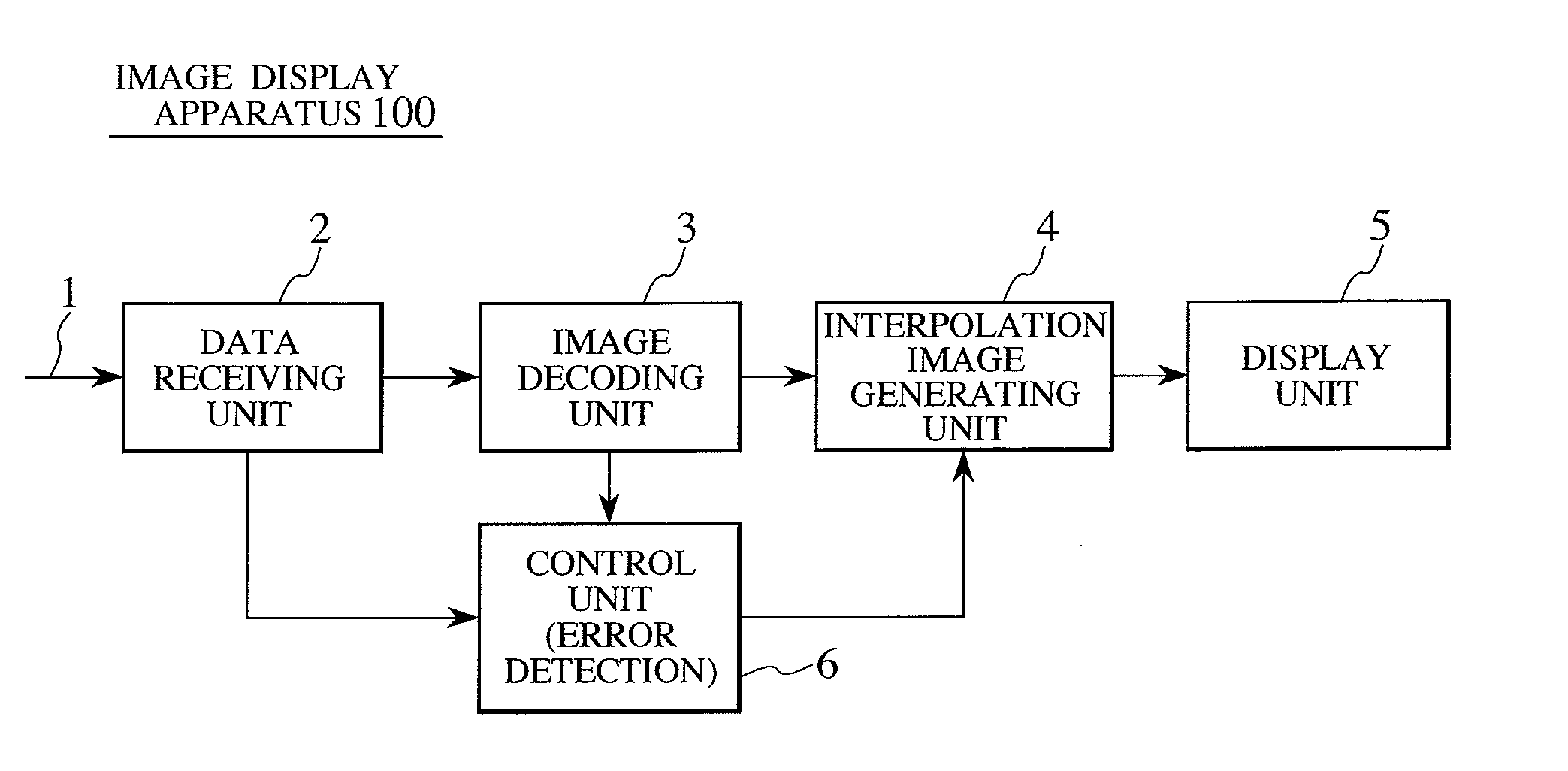
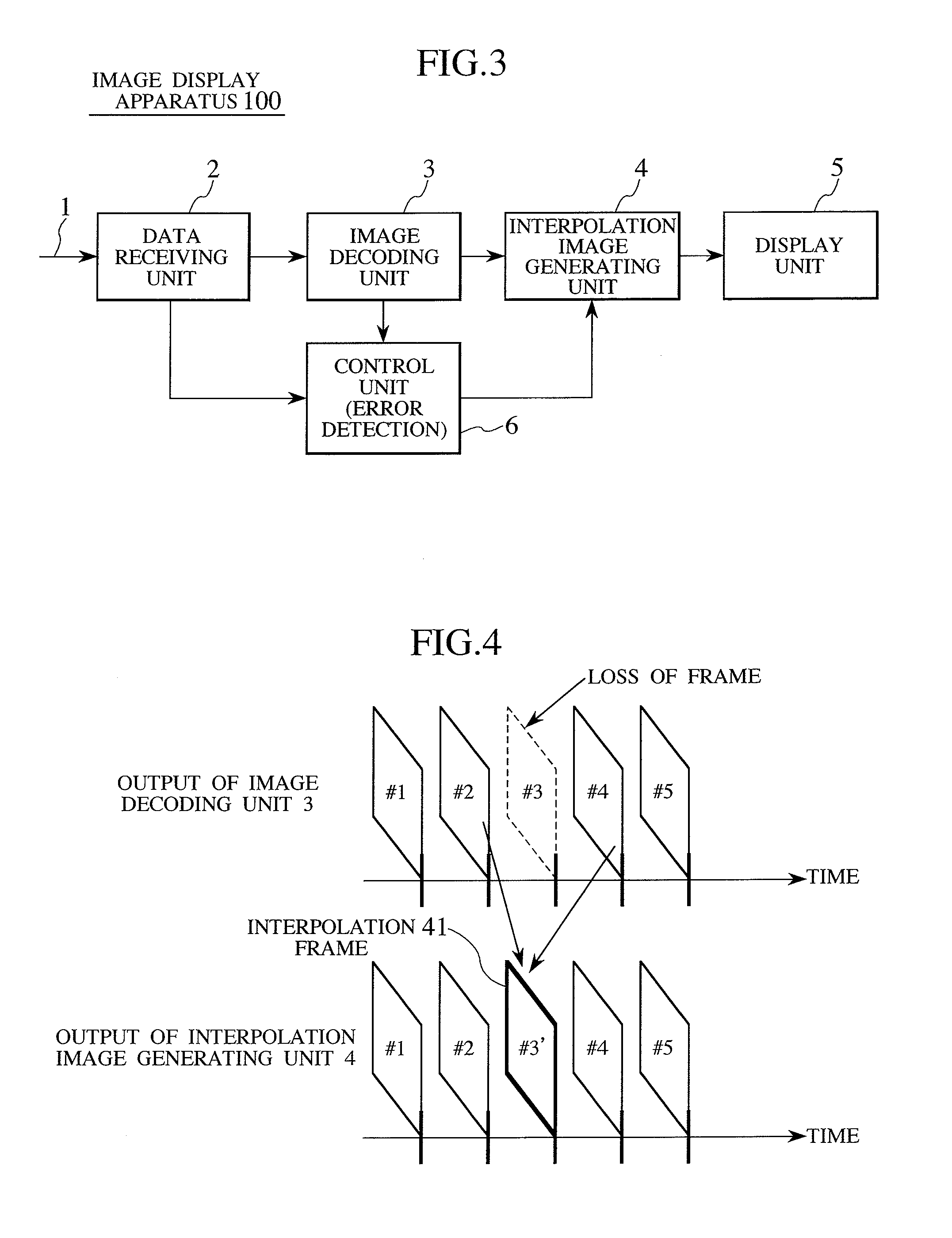
[0012]This allows the image display apparatus to display a complete image frame sequence even when one of the frames is lost due to a transmission error, etc. by replacing the lost frame with the interpolation frame, thereby preventing disturbance and interruption of the image display due to the frame loss.
[0013]Thus, the present invention provides a technique for appropriately compensating for loss of an image frame to allow display of a high quality image.

Problems solved by technology

If this ID data is corrupted due to an uncorrectable error, the entire image frame may need to be discarded or may be lost.
The above patent publications do not take into account the fact that all data (packets) constituting one frame might be corrupted or lost, and therefore cannot handle such frame loss.
Therefore, if an entire frame is corrupted or lost, these techniques cannot appropriately restore (or conceal) its macroblocks by interpolation, etc. since there is no uncorrupted macroblock and hence no motion vector available for that purpose.

Method used


Image

  • Image display apparatus
  • Image display apparatus
  • Image display apparatus

Examples


first embodiment

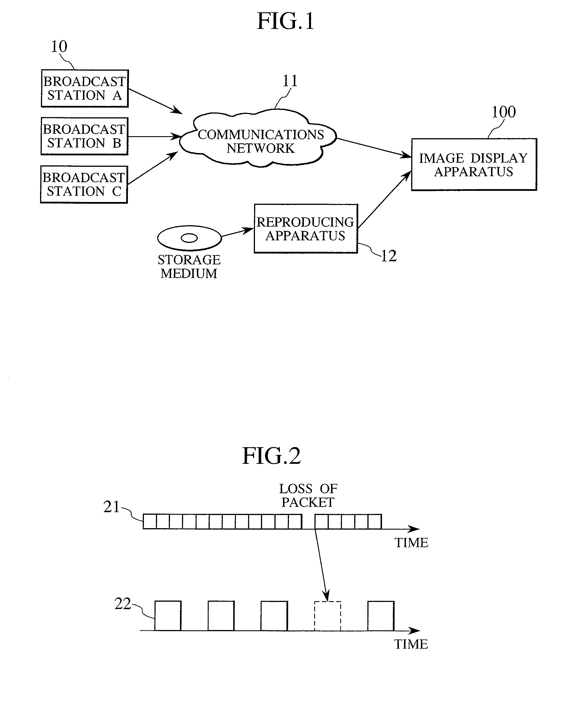
[0028]FIG. 1 shows an exemplary application of an image display apparatus 100 according to a first embodiment of the present invention. Referring to the figure, the image display apparatus 100 receives an encoded stream made up of encoded image and sound data, etc. from broadcast stations 10A to 10C through a communications network 11 in IP broadcasting. Further, the image display apparatus 100 can be connected to an external reproducing apparatus 12 (a HDD player, a DVD player, etc.) so as to receive an encoded stream read from a storage medium (a DVD, etc.) by the external reproducing apparatus 12.

[0029]It should be noted that the encoded stream supplied through the communications network 11 or supplied from the reproducing apparatus 12 is generated according to a syntax specified by MPEG-2, MPEG-4, H.264 / AVC, etc. However, as the encoded stream is transmitted through the communications network 11, it may suffer a transmission error. Further, when the encoded stream is read from t...

second embodiment

[0055]A second embodiment of the present invention will now be described. The second embodiment differs from the first embodiment in that the second embodiment creates an interpolation frame regardless of the presence or absence of a lost or corrupted frame, whereas the first embodiment creates a interpolation frame only when a frame has been corrupted or lost. The second embodiment may be applied to an image display apparatus having a function to vary its image frame rate by periodically inserting interpolation frames into a received image frame sequence. FIG. 8 shows an exemplary configuration of such an image display apparatus.

[0056]Specifically, FIG. 8 shows an interpolation image generating unit 4 according to the present embodiment. The interpolation image generating unit 4 of the present embodiment differs from that of the first embodiment in that it additionally includes a second switch 81 controlled by a control signal from the control unit 6. The second switch 81 selects e...

third embodiment

[0065]The image display apparatuses of the first and second embodiments described above are designed to replace an entire lost frame by frame interpolation. However, the present invention can also be applied to replace a lost portion of an image frame by interpolation. FIG. 10 shows an exemplary process.

[0066]For example, referring to FIG. 10, assume that a macroblock in the frame #3 has suffered an uncorrectable error and hence the image in the macroblock cannot be decoded. This means that that image portion of the frame #3 is lost. According to the present embodiment, this lost image portion is replaced with an interpolation image portion created based on two frames, one immediately preceding and the other immediately succeeding the frame #3. This interpolation image portion is generated by a circuit similar to that of the first embodiment described with reference to FIG. 5 and in a manner similar to that described with reference to FIG. 7. Specifically, the image signal in the fr...


PUM


Abstract

An object of the present invention is to provide a technique of appropriately compensating for loss of even an entire image frame due to data error such as a transmission error to allow display of a high quality image. An image display apparatus of the present invention comprises: a decoding unit which decodes an encoded bit stream into an image signal; an interpolation image generating unit which generates an interpolation frame based on frames of the decoded image signal; and a control unit which detects an error in the encoded bit stream and controls the interpolation image generating unit; wherein when a frame of the encoded bit stream is lost (that is, it has not been able to be decoded) due to an uncorrectable error, the above interpolation frame is displayed instead of the lost frame.

Description

CLAIM OF PRIORITY[0001]The present application claims priority from Japanese application serial no. JP 2006-112897, filed on Apr. 17, 2006, the content of which is hereby incorporated by reference into this application.BACKGROUND OF THE INVENTION[0002](1) Field of the Invention[0003]The present invention relates to an image display apparatus capable of decoding an encoded bit stream and displaying it.[0004](2) Description of the Related Art[0005]In IP broadcasting, an image is compressively encoded (i.e., encoded and compressed) according to a syntax specified by MPEG-2, H.264 / AVC, etc. into an encoded bit stream, which is transmitted through a network, etc. At that time, if the encoded bit stream has suffered a transmission error, it is usually corrected by, for example, FEC (Forward Error Correction). However, the error may be of the type that cannot be corrected even by such an error correction technique. In that case, the erroneous data (portion) is discarded and hence is not su...

Claims


Application Information

Patent Timeline
Patent Type & Authority Applications(United States)
IPC IPC(8): G09G5/00H04N7/173H04N19/132H04N19/134H04N19/139H04N19/196H04N19/44H04N19/50H04N19/503H04N19/51H04N19/513H04N19/587H04N19/65H04N19/89H04N19/895H04N21/238H04N21/2743H04N21/438H04N21/4402H04N21/4425
CPCG09G5/006G09G2320/0261G09G2320/10H04N19/895H04N19/44H04N19/587H04N19/132
Inventor HAMADA, KOICHIKAGEYAMA, MASAHIROYAMAGUCHI, MUNEAKI
Owner MAXELL HLDG LTD
Learn More