Progressive Ophthalmic Lens

a technology of ophthalmology and lens, applied in the field of ophthalmology, can solve the problems of different power correction values and no far vision, and achieve the effect of convenient prescribing and easy to tolera

Active Publication Date: 2007-10-18
ESSILOR INT CIE GEN DOPTIQUE
View PDF3 Cites 6 Cited by
  • Summary
  • Abstract
  • Description
  • Claims
  • Application Information

AI Technical Summary

Benefits of technology

[0010] The invention discloses a lens which is more easily tolerated than standard ophthalmic lenses and easier to prescribe; it makes it possible to provide the wearer with the advantages of a far-vision unifocal lens and also with intermediate vision. The lens of the invention is in particular suited to presbyopic activities not requiring a fill power progression—typically a power progression less than or equal to 2 diopters. The lens of the invention is in particular suited to activities like driving a vehicle.

Problems solved by technology

For presbyopic wearers, the value of the power correction is different for far vision and near vision, due to the difficulties of accommodation in near vision.
On the other hand, no far vision is available.

Method used


Image

  • Progressive Ophthalmic Lens
  • Progressive Ophthalmic Lens
  • Progressive Ophthalmic Lens

Examples


first embodiment

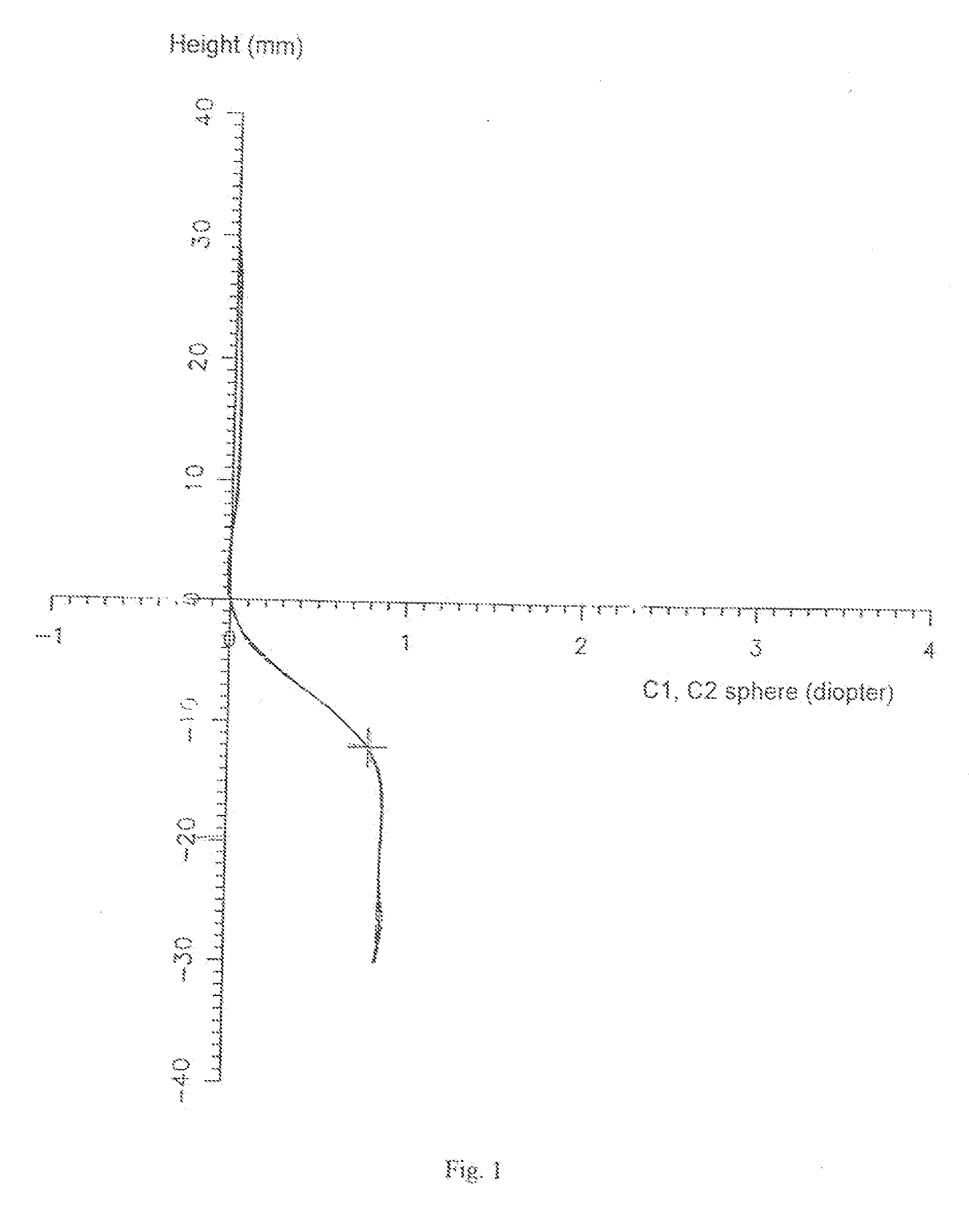
[0050]FIG. 1 shows a diagram of the principal curvatures and of the sphere on the axis of a lens according to the invention. The points on the complex surface of the lens are plotted on FIG. 1—and on FIGS. 2 to 4—relative to an orthonormalized reference frame, the center of which is superposed on the optical center of the lens, the ordinates axis of which is vertical and the abscissa axis is horizontal. In other words, the axis of symmetry of the lens is the ordinates axis. In FIG. 1 the curvature or the sphere is plotted on the abscissa axis in diopters; the position on the lens is marked on the ordinates axis in millimetres. FIG. 1 also shows at the ordinate y=0 mm, the centering point of the lens; this is a point produced on the lens which is used by the optician for fitting the lens in the frame, as explained below.

[0051] The centering point of the lens, considered below, often merges with the geometrical center of the lens before trimming. More generally, the centering point ca...

second embodiment

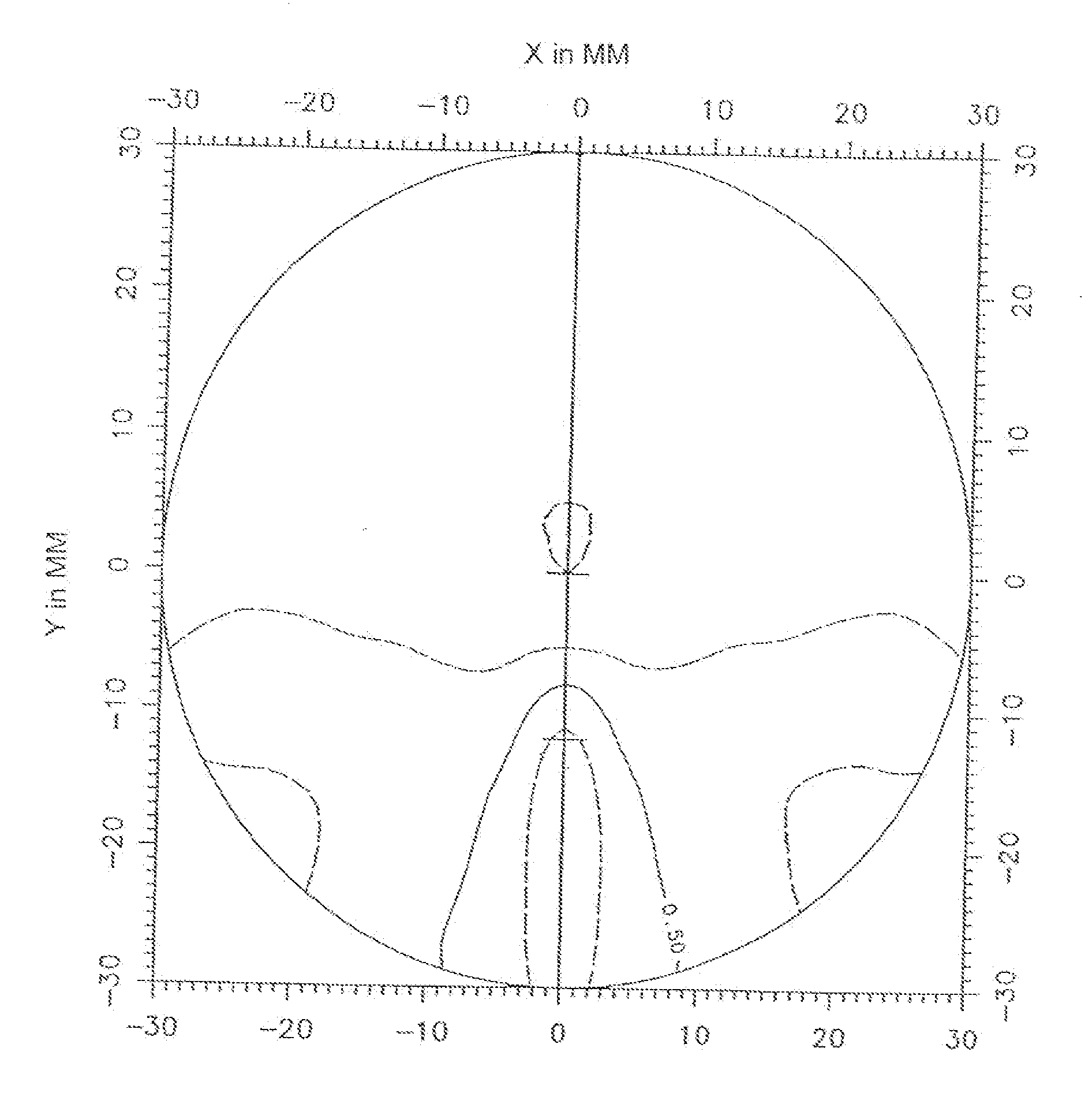
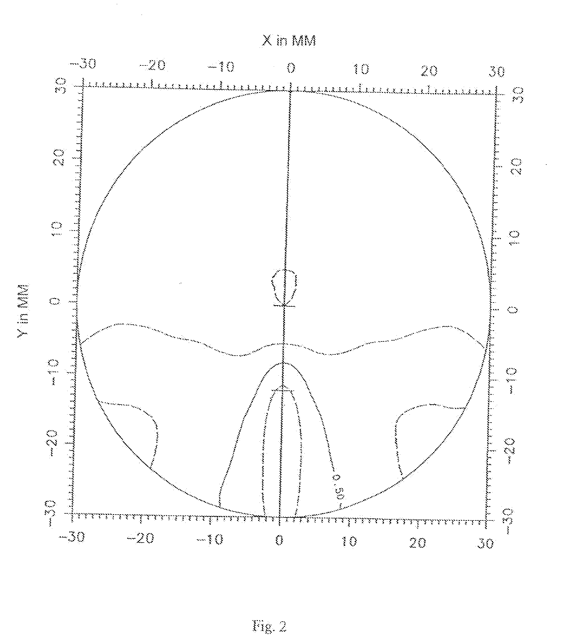
[0076]FIGS. 9 and 10 are similar to FIGS. 4 and 5. Because of the larger value of sphere progression over the surface, cylinder gradient also reaches greater values in the second embodiment than in the first; FIG. 9 shows the 0.50 to 3.00 diopters / mm isoslopes with a pitch of 0.50 diopters / mm. In the far-vision region, defined as indicated above, cylinder slope (or cylinder gradient) is still less than or equal to 0.50 diopters / mm; this inequality is also confirmed in the upper part of the lens for ordinates greater than or equal to 8 mm, whatever the abscissa values. The cylinder gradient is less than 1 diopter / mm for the part of the lens with an ordinate greater than or equal to 5 mm. in the lower right and left parts of the lens, defined as with reference to FIG. 4, the cylinder gradient is also less than or equal to 1 diopter / mm. Finally, cylinder gradient has values less than or equal to 2 diopter / mm over the whole surface of the lens, except over the part of the lens around th...


PUM


Abstract

The invention relates to an ophthalmic lens for long-sighted and intermediate vision comprising a complex surface provided with an optical centre, a substantially umbilicated meridian line and an average size sphere progression on the top surface equal to or greater than 0.50 diopters. The complex surface is provided in the top part thereof with a long-sighted vision area which is formed by cylinder points equal to or less than 0.25 diopters and covers an angular sector focused on the optical centre and whose angle is equal to 160°. Said complex surface also comprises an average size substantially constant sphere on the meridian line in the long-sighted vision area and a progression length equal to or less than 12 mm. Said progression length is defined as a vertical distance between the optical centre and a median point for which the average sphere if greater than 85% of progression on the average sphere in the optical centre. The inventive lens is suitable for driving and prescribed to persons having additional prescription greater than a power progression, whereby a correction adaptable to the power prescription of a longsighted vision person is provided in the top part of the lens. The lower part of the lens ensures the correction needed for an intermediate vision person.

Description

BACKGROUND OF THE INVENTION [0001] The present invention relates to an ophthalmic lens. [0002] Ophthalmic lenses designed to be fitted into a frame involve a prescription. The ophthalmic prescription can include a positive or negative power prescription as well as an astigmatism prescription. Such prescriptions correspond to corrections enabling the wearer of the lenses to correct defects of his or her vision. A lens is fitted in the frame in accordance with the prescription and with the position of the wearer's eyes relative to the frame. [0003] In the simplest cases, the prescription is nothing more than a power prescription. The lens is said to be unifocal and has an axis of symmetry. It is fitted in a simple manner in the frame so that the principal direction of glance of the wearer coincides with the axis of symmetry of the lens. [0004] For presbyopic wearers, the value of the power correction is different for far vision and near vision, due to the difficulties of accommodation...

Claims


Application Information

Patent Timeline
Patent Type & Authority Applications(United States)
IPC IPC(8): G02C7/06G02C7/02
CPCG02C7/06G02C7/066G02C7/063G02C7/061
Inventor CARIMALO, CELINEGUILLOUX, CYRILROLAND, ERIC
Owner ESSILOR INT CIE GEN DOPTIQUE
Why Eureka
Try Eureka