
Wire-grid polarizers, methods of fabrication thereof and their use in transmissive displays

a technology of transmissive display and wire grid, which is applied in the direction of polarising elements, instruments, optics, etc., can solve the problem that plain glass does not transmit 100% of incident light, and achieve the effect of imparting high contrast and brightness characteristics to the display

Inactive Publication Date: 2007-10-18
EI DU PONT DE NEMOURS & CO
View PDF4 Cites 83 Cited by
  • Summary
  • Abstract
  • Description
  • Claims
  • Application Information

AI Technical Summary

Benefits of technology

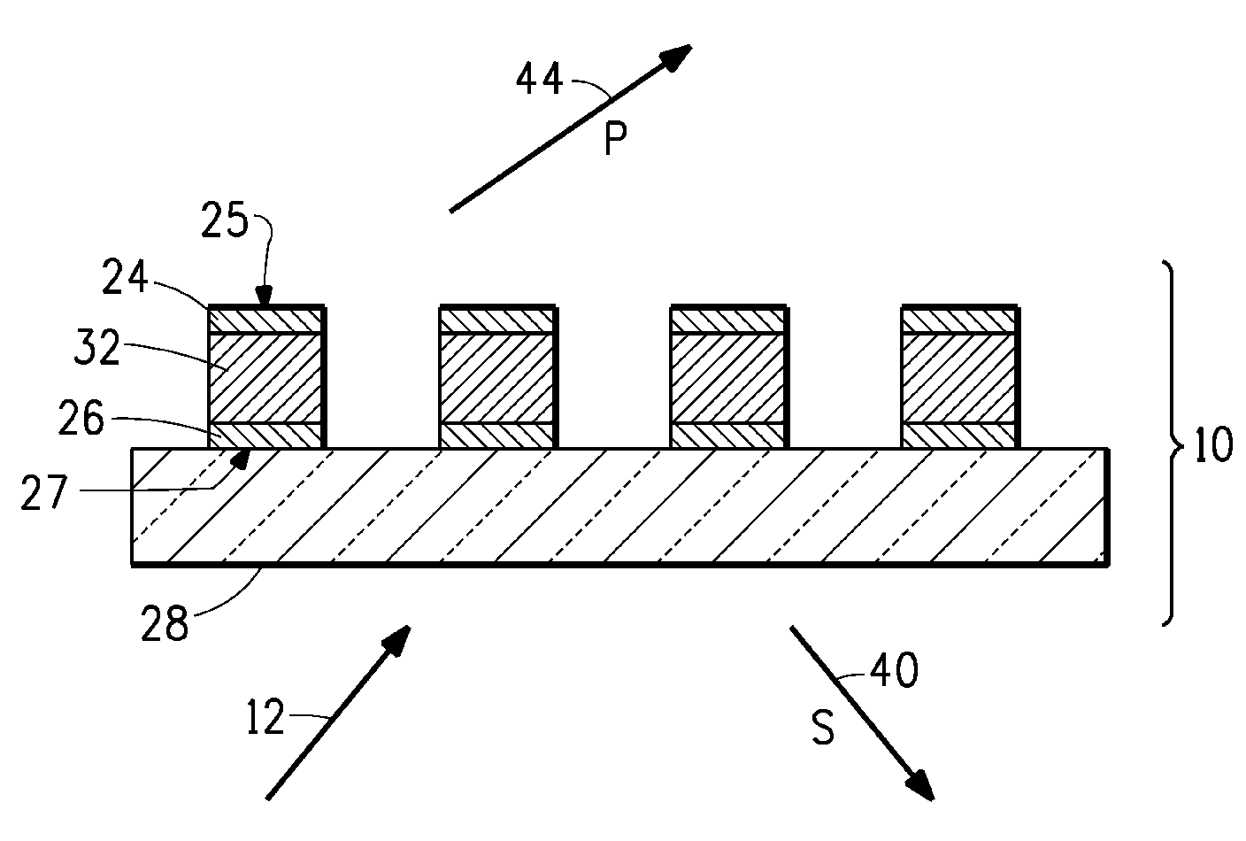
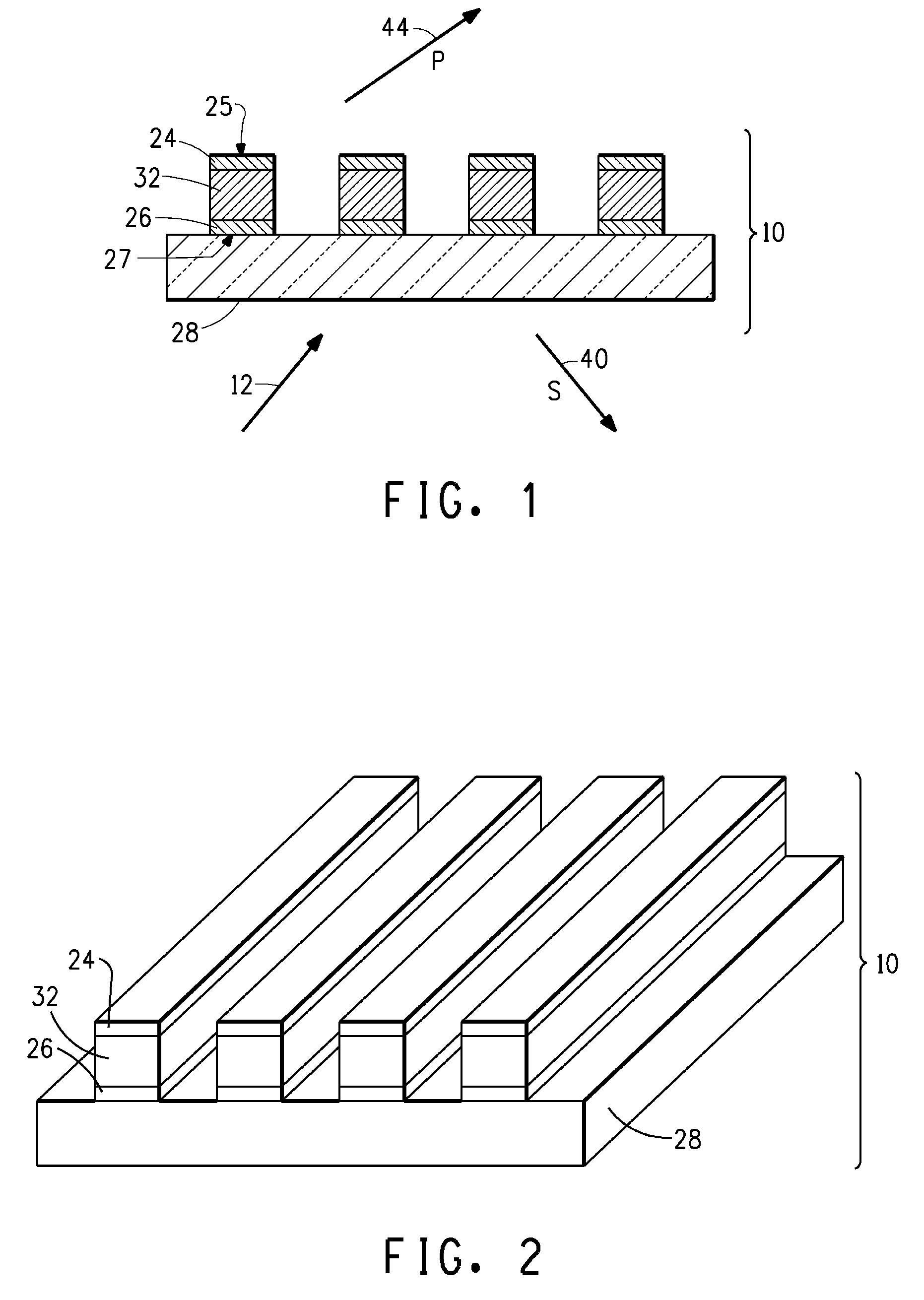
wherein the surface is nearer the display module than the opposing surface. In various embodiments, the light source is capable of producing visible, ultraviolet, and / or infra-red light, and the material of the elements is reflective to visible, ultraviolet, and / or infra-red light, respectively (i.e., material is reflective to light being produced by the light source when being operated). Additional features and advantages of the invention will be apparent from the detailed description which follows, taken in conjunction with the accompanying drawings, which together illustrate, by way of example, features of the invention.

Problems solved by technology

In practice, however, even the most reflective metals used as mirrors absorb some fraction of the incident light and reflect only 90% to 95%, and plain glass does not transmit 100% of the incident light due to surface reflections.

Method used


Image

  • Wire-grid polarizers, methods of fabrication thereof and their use in transmissive displays
  • Wire-grid polarizers, methods of fabrication thereof and their use in transmissive displays
  • Wire-grid polarizers, methods of fabrication thereof and their use in transmissive displays

Examples


example 1

[0058]This sample was made by spin-coating a mixture of one-third Microposit® Type P Thinner (Rohm and Haas Electronic Materials, LLC, Marlborough, Mass.) and two-third Microposit® S1805 Positive Photoresist (Rohm and Haas Electronic Materials, LLC, Marlborough, Mass.) onto a 152 mm×100 mm×2 mm thick piece of soda-lime glass for 30 seconds at 3500 RPM. The plate was then dried on a hotplate at 100° C. for 15 minutes. The plate was placed into a Lloyd's mirror set-up at 56° incident. The plate was exposed using the 364.8 nm line from a Coherent Argon Sabre Laser (Coherent, Inc., Santa Clara, Calif.) for 30 seconds to form an interference sinusoidal interference pattern with a period of 220 nm peak to peak. The sample was then developed in a mixture of 4 parts deionized water and one part Microposit® 351 Developer (Rohm and Haas Electronic Materials, LLC, Marlborough, Mass.) for 20 seconds, rinsed with deionized water for 10 seconds, and dried with forced air. The developed plate was ...

example 2

[0059]This sample was made by spin-coating a mixture of one-third Microposit® Type P Thinner (Rohm and Haas Electronic Materials, LLC, Marlborough, Mass.) and two-third Microposit® S1805 Positive Photoresist (Rohm and Haas Electronic Materials, LLC, Marlborough, Mass.) onto a piece of 200 gauge Melinex® 455 polyethylene terephthalate (PET, DuPont Teijin Films, Hopewell, Va.) taped on all four sides down to a 152 mm×100 mm×2 mm thick piece of soda-lime glass for 30 seconds at 3500 RPM. The plate was then dried on a hotplate at 100° C. for 15 minutes. The plate was placed into a Lloyd's mirror set-up at 56° incident. The plate was exposed using the 364.8 nm line from a Coherent Argon Sabre Laser (Coherent, Inc., Santa Clara, Calif.) for 30 seconds to form an interference sinusoidal interference pattern with a period of 220 nm peak to peak. The sample was then developed in a mixture of 4 parts deionized water and one part Microposit® 351 Developer (Rohm and Haas Electronic Materials, L...


PUM


Abstract

Wire-grid polarizers (WGPs) and their use in transmissive displays are disclosed. The displays containing these WGPs possess high contrast and brightness characteristics in comparison to prior art displays.

Description

FIELD OF THE INVENTION[0001]The present invention relates to wire-grid polarizers (WGPs), methods for fabrication of WGPs, and use of WGPs in transmissive displays.BACKGROUND OF THE INVENTION[0002]WGPs are optical devices that serve to transmit light of a specific polarization while reflecting light of the orthogonal polarization.[0003]The use of an array of parallel conducting wires to polarize radio waves dates back more than 110 years. Wire grids, generally in the form of an array of thin parallel conductors (unsupported or supported by a transparent substrate), have also been used as polarizers for the infrared portion of the electromagnetic spectrum.[0004]The key factor that determines the performance of a wire grid polarizer is the relationship between the center-to-center spacing, or period, of the parallel grid elements and the wavelength of the incident radiation. If the grid spacing or period is large compared to the wavelength, the grid functions as a diffraction grating,...

Claims


Application Information

Patent Timeline
IPC IPC(8): G02B5/30
CPCG02B5/3058G02B6/0051G02F1/133536G02B6/0056G02B6/0055G02B5/30
Inventor MACMASTER, STEVEN WILLIAM
Owner EI DU PONT DE NEMOURS & CO
Learn More