Color image forming apparatus

a technology of color image and forming apparatus, which is applied in the direction of electrographic process apparatus, instruments, optics, etc., can solve the problems of black photoconductor rapid deterioration, color misregistration becomes noticeable, image quality deterioration, etc., and achieve the effect of suppressing pitch fluctuation

Inactive Publication Date: 2007-10-18
SHARP KK
View PDF7 Cites 26 Cited by
  • Summary
  • Abstract
  • Description
  • Claims
  • Application Information

AI Technical Summary

Benefits of technology

[0018]Since the image forming apparatus of the present invention includes the correction signal output section for outputting the speed correction signal to correct a periodic pitch fluctuation included in each formed image and the drive control section for controlling the driving section to correct the driving speed of each photoconductor by the speed correction signal, wherein the speed correction signal is a signal having the same cycle as a rotational cycle of each photoconductor, the pitch fluctuation having the same cycle as a rotational cycle of each photoconductor is corrected, thereby an image having suppressed pitch fluctuation can be obtained. A pitch fluctuation is included in each image of each color respectively, and is recognized as a color misregistration. Accordingly, with the image forming apparatus of the present invention, an image with little color misregistration can be obtained.

Problems solved by technology

When the color misregistration is great, it might be evaluated that the image quality is deteriorated.
When the phases of pitch fluctuations caused by the eccentricity of each photoconductor are not matched on the output image, the color misregistration becomes noticeable.
In such an image forming apparatus, when a ratio of occupancy of the monochromatic image formation to an entire body is large, only black photoconductor is deteriorated rapidly.
In this case, unbalance is generated at a maintenance time of each photoconductor of monochromatic color and others (yellow, cyan, and magenta).
Since the rotational cycle of the black photoconductor is different from those of the other photoconductors, the technique for matching the direction of the eccentricity to make the color misregistration unnoticeable cannot be taken.
Meanwhile, in the case of generating correction patterns of the number of the photoconductors to cancel a speed fluctuation of one rotation of the photoconductor, the configuration is complicated and the cost is disadvantageously increased in most cases.

Method used


Image

  • Color image forming apparatus
  • Color image forming apparatus
  • Color image forming apparatus

Examples


Embodiment Construction

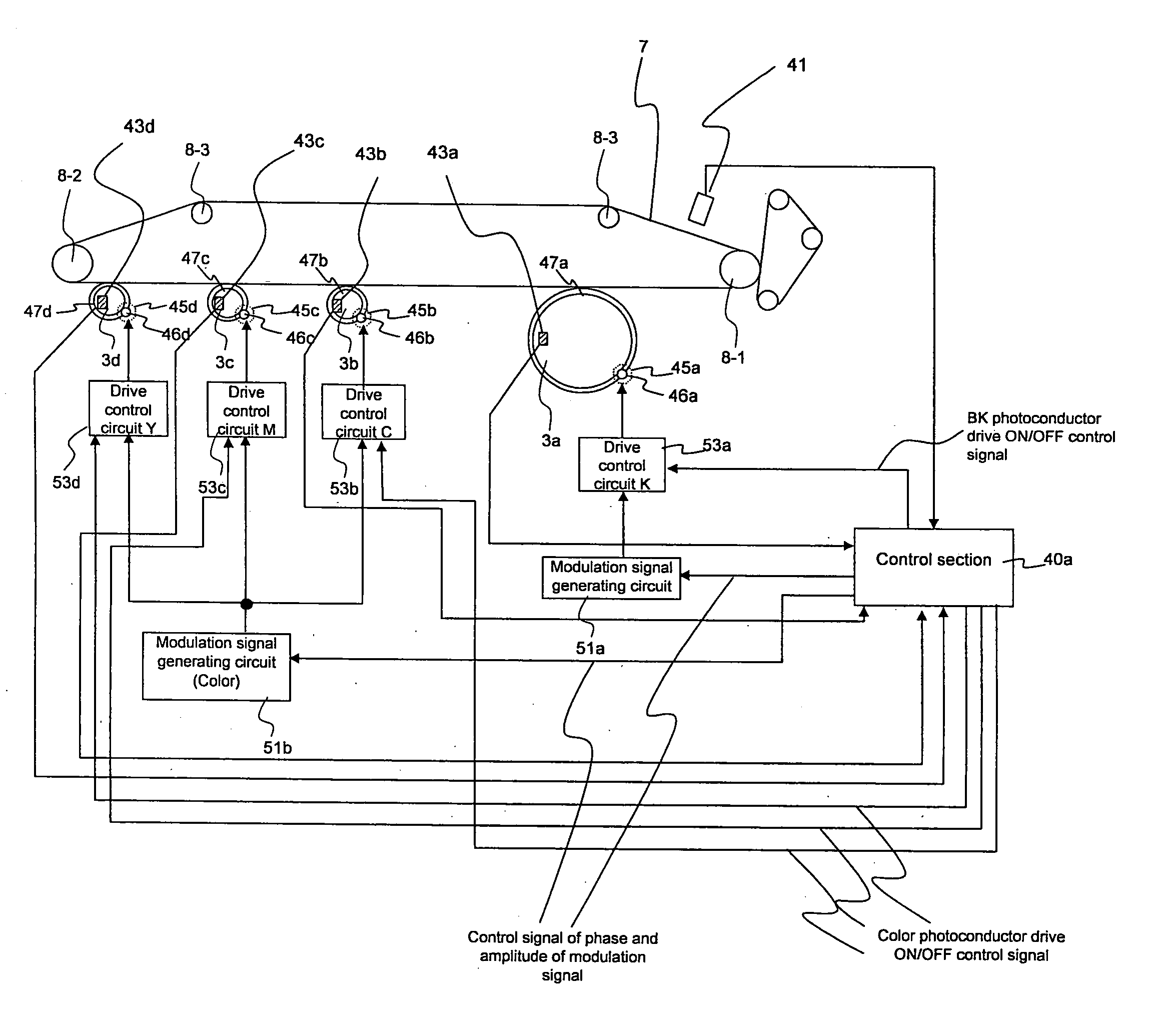
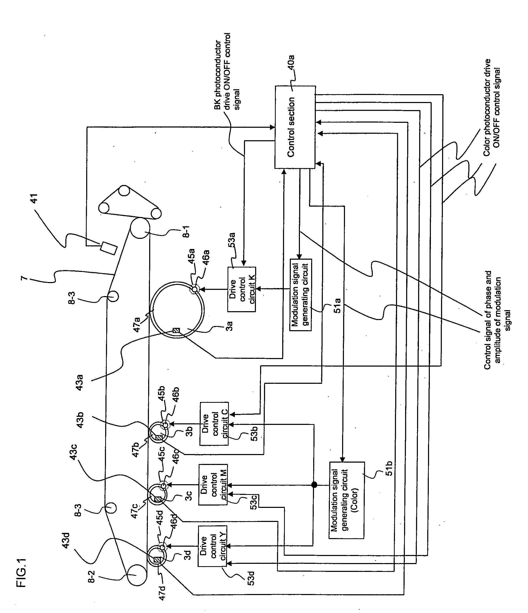
[0056]In the image forming apparatus of the present invention, the image pitch refers to an interval of dots (pixels) constituting the image, and in this specification, particularly, refers to the interval of the pixels along a moving direction of a periphery of each photoconductor drum. Although each pixel must be aligned at a predetermined interval (reference pitches), the image prepared on the image forming apparatus includes partially different image pitches, namely, includes a periodic fluctuation component (pitch fluctuation component). It can be so considered that the fluctuation of the image pitches is mainly generated by an eccentricity of the photoconductor drum or its driving gear. Namely, a peripheral speed of the photoconductor drum is fluctuated by the eccentricity, and this fluctuation is expressed as the fluctuation of the image pitches.

[0057]An entire part of or a part of the correction signal output section, the drive control section, and the correction signal gene...


PUM


Abstract

A color image forming apparatus including: a plurality of drum-type photoconductors for forming an image in a different color on each peripheral surface and the photoconductors having at least two different diameters; a plurality of driving sections for driving each photoconductor at a driving speed in accordance with the diameter so that each photoconductor rotates at a predetermined peripheral speed; a correction signal output section for outputting a speed correction signal to correct a periodic pitch fluctuation included in each formed image; and a drive control section for controlling the driving section to correct the driving speed of each photoconductor by the speed correction signal, wherein the speed correction signal is a signal having the same cycle as a rotational cycle of each photoconductor.

Description

CROSS-REFERENCE TO RELATED APPLICATION[0001]This application is related to Japanese patent application Nos. 2006-112585 and 2006-349824 which are filed on Apr. 14, 2006 and Dec. 26, 2006 respectively whose priorities are claimed under 35 USC § 119, the disclosure of which are incorporated by reference in its entirety.BACKGROUND OF THE INVENTION[0002]1. Field of the Invention[0003]The present invention relates to a color image forming apparatus.[0004]2. Description of the Related Art[0005]There has been known a color image forming apparatus (so-called tandem-type color image forming apparatus) having a plurality of drum-type photoconductors. In the color image forming apparatus, it is important to suppress the positional deviation for every color (color misregistration) to an unnoticeable degree. When the color misregistration is great, it might be evaluated that the image quality is deteriorated. The greatest factor of the color misregistration is a periodic crude density on the out...

Claims


Application Information

Patent Timeline
Patent Type & Authority Applications(United States)
IPC IPC(8): G03G15/00
CPCG03G15/5008G03G2215/0119G03G15/0194G03G2215/0161G03G2215/0132
Inventor KIKUCHI, YOSHITERUHARADA, YOSHIKAZUTOMITA, NORIOMATSUYAMA, KENGOEBA, YUTAKAITO, TETSUSHI
Owner SHARP KK
Why Eureka
Try Eureka